background image

This manual is the intellectual property of FOXCONN, Inc. Although the

information in this manual may be changed or modified at any time, FOXCONN
does not obligate itself to inform the user of these changes.

Trademark:

All trademarks are the property of their respective owners.

Version:

User Manual V1.0 in English for 761GXM2MA series motherboard.

Symbol description:

       Note:

 refers to important information that can help you to use motherboard

       better.

Attention:

 indicates that it may damage hardware or cause data loss,

and tells you how to avoid such problems.

Warning: 

means that a potential risk of property damage or physical

injury exists.

Statement:

More information:

If you want more information about our products, please visit FOXCONN

website:  http://www.foxconnchannel.com

PDF 

文件使用

 "pdfFactory" 

试用版本创建


www.fineprint.com.cn

Summary of Contents for 761GXM2MA series

Page 1: ...User Manual V1 0 in English for 761GXM2MA series motherboard Symbol description Note refers to important information that can help you to use motherboard better Attention indicates that it may damage...

Page 2: ...aracteristics of information technology equipment EN 61000 3 2 2000 Electromagnetic compatibility EMC Part 3 Limits Section 2 Limits for harmonic current emissions equipment input current 16A per phas...

Page 3: ...cturer HON HAIPRECISION INDUSTRY COMPANYLTD Address 66 CHUNG SHAN RD TU CHENG INDUSTRIAL DISTRICT TAIPEI HSIEN TAIWAN R O C Supplementary Information This device complies with Part 15 of the FCC Rules...

Page 4: ...20 BIOS Features 22 Advanced BIOS Features 23 Advanced Chipset Features 26 Integrated Peripherals 30 Power Management Setup 34 PnP PCIConfigurations 37 PC Health Status 38 Frequency Voltage Control 3...

Page 5: ...Table of Contents Directions for Bundled Software TIGER ONE 46 Fox LiveUpdate 52 Chapter 5 5...

Page 6: ...ure to switch off the DC power supply may result in serious damage to your system or memory module Attention We cannot guarantee that your system will operate normally while over clocked Normal operat...

Page 7: ...ard 10 100M LAN K with onboard Gigabit LAN R with RAID S with SATA 2 with DDR2 H comply with RoHS directive You can find PPID label on the motherboard It indicates the functions that the motherboard h...

Page 8: ...ior performance reliability and quality at a reasonable price This motherboard adopts the advanced SiS 761GX 966 966L chipset providing users a computer platform with a high integration compatibility...

Page 9: ...pports up to 4GB DDR2 memory USB 2 0 Ports l Supports hot plug l Eight USB 2 0 ports four rear panel ports two onboard USB headers providing four extra ports l Supports wake up from S1 S3 S4 and S5 mo...

Page 10: ...figuration and Power Interface l Supports S0 normal S1 power on suspend S3 suspend to RAM S4 suspend to disk depends on OS and S5 soft off Expansion Slots l Two PCI slots l One PCI Express X1 slot l O...

Page 11: ...11 SPI Connector optional 12 IDE Connectors 13 FDD Connector 14 ATX 24 pin Connector 15 INTR Connector 16 IrDA Connector 17 DDR DIMM Slots 18 CPU Socket 19 North Bridge SiS 761GX 20 ATX 12V Power Con...

Page 12: ...fer to the red Microphone output Line in Line out Microphone rear CEN LFE Side Jacks for 8 channel models When using an 8 channel sound source connect the front speaker to the green audio output conne...

Page 13: ...hard drive and floppy drive data cables and setting up various other feature of the motherboard Caution should be exercised during the installation process Please refer to the motherboard layout prio...

Page 14: ...the socket by pressing the le ver sideways then lift it up to a 90o angle 2 Align the cut edge to the gap in the base of the socket Carefully insert the CPU into the socket until it fits in place 3 Wh...

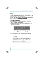
Page 15: ...There is only one gap in the center of the DIMM slot and the memory module can be fixed in one direction only 2 Align the memory module to the DIMM slot and insert the module vertically into the DIMM...

Page 16: ...or on the motherboard Firmly plug the power supply cable into the con nector and make sure it is secure Attention W e recommend you use 24 pin power supply If you want to use 20 pin power supply you n...

Page 17: ...ble s blue connector to the primary recommended or second ary IDE connector then connect the gray connector to the slave device hard disk drive and the black connector to the master device Other Conne...

Page 18: ...ws your com puter to send and receive data via an infrared ray The relevant parameters for the BIOS Inte grated Peripherals should be set prior to using this function F_USB1 2 D D Empty GND VCC VCC GN...

Page 19: ...f headphones are plugged into the front panel of the chassis using the Front Audio then the Line out Rear Audio on the rear panel will not work If you do not want to use the Front Audio pin 5 and 6 pi...

Page 20: ...ects to the chassis secu rity switch on the case The system can detect the chassis intrusion through the status of this connector if the connector has been closed once the system will send a message T...

Page 21: ...ing PCI drivers and software and Operating Systems High Bandwidth per Pin Low overhead Low latency PCI Express supports a raw bit rate of 2 5 Gb s on the data pins This results in a real bandwidth per...

Page 22: ...ngs for the card 2 Make sure to unplug the power cord before adding or removing expansion cards 3 Align the card connector with the slot and press firmly until the card is completely seated on the slo...

Page 23: ...should refer to this when adjusting jumper settings Jumper Diagram Definition Description 1 2 Set pin 1 and pin 2 closed 2 3 Set pin 2 and pin 3 closed Closed Set the pin closed Open Set the pin opene...

Page 24: ...s 2 You want to change the default CMOS settings This chapter includes the following information v Enter BIOS Setup v Main Menu v Standard CMOS Features v BIOS Features v Advanced BIOS Features v Adva...

Page 25: ...o enter SETUP ESC to enter Boot Menu Main Menu The main menu allows you to select from the list of setup functions and two exit choices Use the arrow keys to select among the items and press Enter to...

Page 26: ...PCI settings and parameters can be modified through this menu PC Health Status This will display the current status of your PC Frequency Voltage Control Frequency and voltage settings can be adjusted...

Page 27: ...is option allows you to set up the desired time usually as the current time with hour minute second format IDE Channel 0 1 Master Slave Channel 2 3 Master These categories identify the HDD types of 4...

Page 28: ...80 Color Graphic Adapter powering up in 80 column mode MONO Monochrome adapter including high resolution monochrome adapters Halt On This category determines whether or not the computer will stop if...

Page 29: ...s with an excellent data protection and HDD recovery function v SuperSpeed CPU Clock The conventional over clock method uses the jumpers on the motherboard and it is both troublesome and apt to errors...

Page 30: ...program wants to write any information to this sector and will give an audible warning Note Such function provides protection to the startup sector only it does not protect the entire hard disk vCPU...

Page 31: ...the typematic delay settings for your keyboard vTypematic Rate Chars Sec Use this item to define how many characters per second a held down key generated vTypematic Delay Msec Use this item to define...

Page 32: ...th no floppy drive select Yes for this item to ensure compatibility with Windows 95 logo certification vVideo BIOS Shadow This item Enabled or Disabled copies video BIOS to shadow DRAM which can impro...

Page 33: ...ntrol Press enter to set the items about HyperTransport Control vOnChip VGA Control Press enter to set the items about OnChip VGA Control vSystem BIOS Cacheable Select Enabled to allow catching of the...

Page 34: ...is used to set the mode of the CKE base power down vCKE base powerdown This item is used to set CKE base powerdown vMemclock tri stating This item is used to set Memclock tri stating vMemory Hole Rema...

Page 35: ...me vRow Cycle Time This item is used to set the time RAS Active to RAS Active or auto refresh of the same bank vRAS active to CAS RW delay This item is used to set the RAS to CAS delay for a read writ...

Page 36: ...Speed The available setting values are 200MHz 400MHz 600Mhz and 800MHz Onchip VGA Control Memu vVGA Share Memory Size This option selects the size of on chip frame buffer for vga output vGraphics Eng...

Page 37: ...hip PCI device vOnboard SuperIO Device Press enter to set onchip onboard SuperIO device vIDE HDD Block Mode This item is used to set whether the IDE HDD Block Mode is allowed vIDECH0 1 2 3 Access Inte...

Page 38: ...IDE devices Choose Auto to let the system auto detect which PIO mode is the best or select a PIO mode from 0 4 vPrimary Secondary Master Slave UItraDMA UItraDMA technology provides faster access to I...

Page 39: ...r Select This option is used to set audio controller vSiS Serial ATA Controller This option is used to enable or disable SiS serial ATA controller vSiS Serial ATA Mode This option is used to set Seria...

Page 40: ...ined by the infrared module installed on the board vUR2 Duplex Mode This option is available when UART 2 mode is set to either ASKIR or IrDA This option enables you to determine the infared function o...

Page 41: ...e the power supply only for the main parts after a delay period The status of the computer before it enters STR will be saved in memory and the computer can quickly return to previous status when the...

Page 42: ...ower button override vPower State Resume Control This option is used to set the power state resume vPM Wake Up Events Press enter to set the items of PM Wake Up Events vACPIAWAY Mode This option is us...

Page 43: ...k vPower Up By Alarm This option is used to enable or disable the feature of boot up the system on a scheduled time date When it set as Enabled the following three items can be used vMonth Alarm It is...

Page 44: ...rces If the ISA cards you installed not supporting PnP you will need to select Manual and manually adjust interruption re sources in the event of hardware conflicts However since this motherboard has...

Page 45: ...ll give off warning vCPU Vcore 3 3V 5V 12V CPU Temp Systerm Temperature CPU FAN Speed Systerm FAN Speed These items display the current status of all of the monitored hardware device components such a...

Page 46: ...an unused PCI slot will be disabled to reduce electromagnetic interference vSpread Spectrum If you enable spread spectrum it can significantly reduce the EMI ElectroMagne tic Interference generated by...

Page 47: ...by your hardware devices it will cause system to make mistakes or not stable If you only want to load the optimized defaults in an option you can select this option and press the key F7 Set Superviso...

Page 48: ...center of screen Quit Without Saving Y N Y At this time press Y to exit CMOS but it does not save your amendment in CMOS press N ESC to return main menu Under the menu Advanced BIOS Features Setup if...

Page 49: ...CD that comes with the motherboard contains useful software and several utility drivers that enhance the mother board features This chapter includes the following information v Utility CD content v S...

Page 50: ...the drivers for your motherboard You should install the drivers sequentially from first to last A SiS Chipset Driver B Realtek HDA Audio Driver C Realtek LAN Driver D SiS VGA Driver E SiS RAID Driver...

Page 51: ...manual or auto Click the driver that you want to install and begin the steps by manual Or you just click One Click Setup button to install the driver by auto after install SiS Chipset Driver Installi...

Page 52: ...Chapter 4 Driver CD Introduction 45 This chapter will introduce how to use attached software This chapter provides the following information v TIGER ONE v Fox LiveUpdate 5 5 Chapter...

Page 53: ...ou can Modify system performance settings such as bus speeds CPU voltages fan speed and other system performance options that are supported by the BIOS Monitor hardware temperature voltage frequency a...

Page 54: ...n to exit the program Minimum Click this button to minimize the window Configuration Click this button to configurate the parameters for the program It determines which items will be shown in shorten...

Page 55: ...ts you set memory and PCI Express frequency by manual Close this page Reset the changes Go to Freq page Close this page Reset the changes Apply the changes Select the option you want to set Adjust by...

Page 56: ...able alert function when the CPU temperature is higher than high limit value Show current high limit value of CPU temperature 4 2 Limit Setting Sys Temp This page lets you to set system high limit tem...

Page 57: ...Enable alert function when the CPU fan rev is lower than low limit rpm value Show current low limit rpm value of CPU fan 4 4 Limit Setting Sys Fan This page lets you to set system low limit rpm and en...

Page 58: ...Software 51 5 Fan Page Fan Control This page lets you enable smart Fan function or set fan speed by manual Go to Fan page Set fan speed by dragging the lever Enable or disable smart fan function Rese...

Page 59: ...e system BIOS drivers and utilities by local or online Supported Operating Systems Windows 2000 Windows XP 32 bit and 64 bit Windows 2003 32 bit and 64 bit Using Fox LiveUpdate 1 1 Local Update BIOS I...

Page 60: ...ame Click here 1 3 Local Update Update This page lets you update your system BIOS from Internet After click Update there will show warning message please read it carefully If you still want to continu...

Page 61: ...you update your system BIOS from Internet Click start it will search the new BIOS from Internet Then follow the wizard to finish the update operation Click here Current information Search new BIOS fr...

Page 62: ...r system drivers from Internet Click start it will search the new drivers from Internet Then follow the wizard to finish the update operation Click here Current information Search new drivers from Int...

Page 63: ...net Then follow the wizard to finish the update operation Click here Current information Search all new BIOS drivers utilities from Internet 2 3 Online Update Update Utility This page lets you update...

Page 64: ...tart searching and related information will show on the task bar Click here Set auto search options Select search which kind of versions Apply the changes Reset to default value Note When enable auto...

Page 65: ...ut Fox LiveUpdate 3 2 Configure System This page lets you set the backup BIOS location and change different skin of the utility Click here Set the location of download files or auto backup BIOS Determ...

Reviews: