Chapter 1 Product Introduction
4
865G/GV/PE7MC User Manual
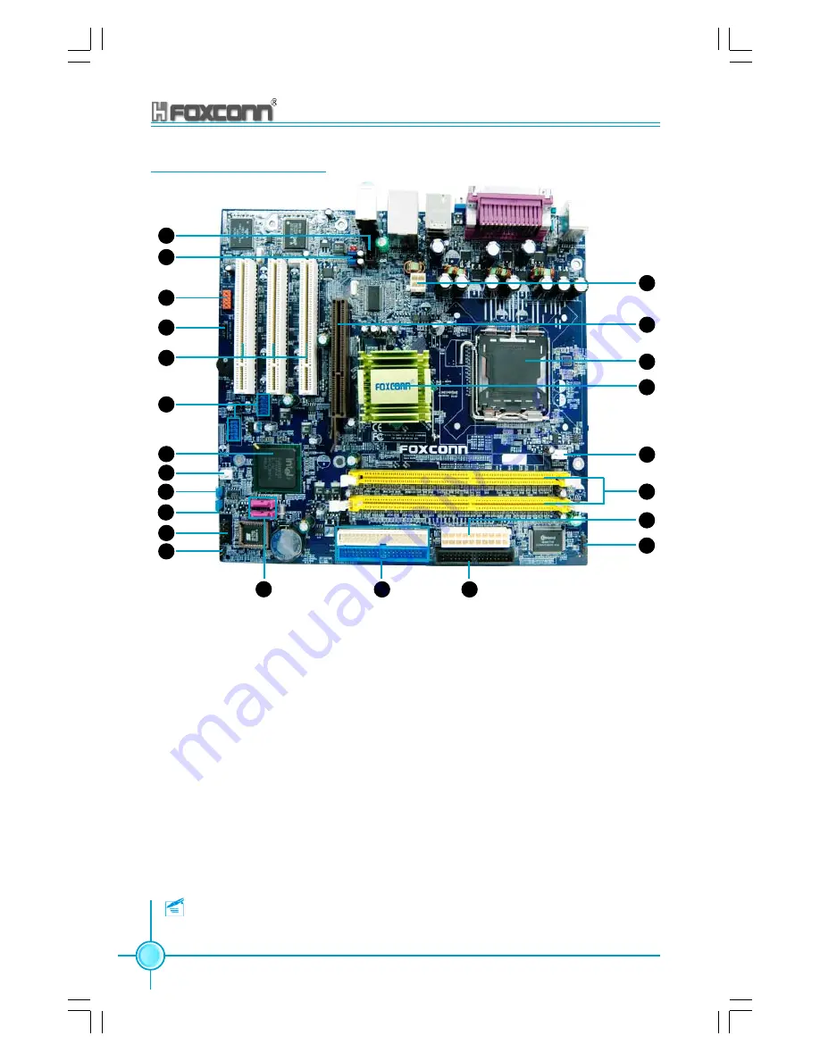
865G/GV/PE7MC Layout
Note:
The above motherboard layout is provided for reference only;
please refer to the physical motherboard.
1.CD_IN connector
2.Front Audio connector
3.1394 header
4.SPDIF_OUT connector
5.PCI slots
6.USB headers
7.South Bridge: ICH5 chipset
8.FAN1 connector
9.Clear CMOS jumper
10.BIOS protection jumper
11.Front panel connector
12.Chassis intruder connector
13.Serial ATA connectors
14.IDE connectors
15.FDD connector
16.IrDA header
17.20-pin ATX power connector
18.184-pin DIMM slots
19.CPU FAN connector
20.North Bridge: 865G/GV/PE chipset
21.CPU socket
22.AGP slot (only for 865G/PE7MC)
23.4-pin ATX_12V power connnector
1
2
3
4
5
6
7
8
9
10
11
12
13
14
15
16
17
18
19
20
21
22
23


