background image

91

5

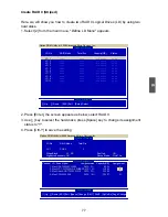
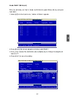
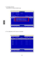
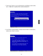
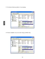
7. There are two drivers, for your 32-bit XP system, press [Enter] to select the first 

driver - "AMD AHCI Compatible RAID Controller-x86 platform".

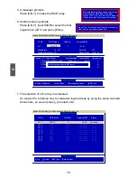
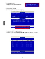
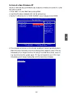
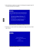
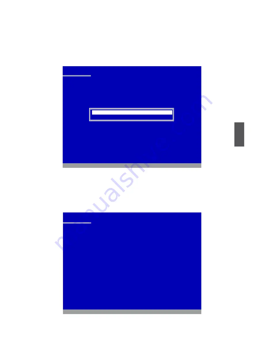
8. A confirmation message appears to double check if the driver is really what we 

wanted, press <Enter> to continue. 

Windows Setup


  Setup will load support for the following mass storage device(s):

        AMD AHCI Compatible RAID Controller-x86 platform

      * To specify additional SCSI adapters, CD-ROM drivers, or special 

        disk controllers for use with Windows, including those for 

        which you have a device support disk from a mass storage device 

        manufacturer, press S.

      * If you do not have any device support disks from a mass storage

         device manufacturer, or do not want to specify additional

        mass storage devices for use with Windows, press ENTER.

  S=Specify Additional Device         ENTER=Continue        F3=Exit
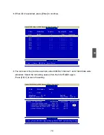
Windows Setup


You have chosen to configure a SCSI Adapter for use with Windows,

using a device support disk provided by an adapter manufacturer.

Select the SCSI Adapter you want from the following list, or press ESC

to return to the previous screen.


   ATI AHCI Compatible RAID Controller-x86 platform

   AMD AHCI Compatible RAID Controller-x64 platform

AMD AHCI Compatible RAID Controller-x86 platform

  ENTER=Select     F3=Exit

Summary of Contents for A76ML Series

Page 1: ...A7VML A76ML Series Motherboard User s Manual ...

Page 2: ...ol indicates that this product may not be treated as household waste By ensuring this product is disposed of correctly you will help prevent potential negative consequences for the environment and human health which could other wise be caused by inappropriate waste handling of this product For more detailed information about recycling of this product please contact your local city office your hous...

Page 3: ...ements of radio disturbance characteristics of information technology equipment EN 61000 3 2 2000 Electromagnetic compatibility EMC Part 3 Limits Section 2 Limits for harmonic current emissions equipment input current 16A per phase EN 61000 3 3 A1 2001 Electromagnetic compatibility EMC Part 3 Limits Section 2 Limits of voltage fluctuations and flicker in low voltage supply systems for equipment wi...

Page 4: ...ard Manufacturer HON HAI PRECISION INDUSTRY COMPANY LTD Address 66 CHUNG SHAN RD TU CHENG INDUSTRIAL DISTRICT TAIPEI HSIEN TAIWAN R O C Supplementary Information This device complies with Part 15 of the FCC Rules Operation is subject to the following two conditions 1 this device may not cause harmful interference and 2 this device must accept any interference received including interference that m...

Page 5: ... power please make sure the power supply AC input voltage setting has been configured to the local standard To prevent damage to the motherboard do not allow screws to come in contact with the motherboard circuit or its components Also make sure there are no leftover screws or metal components placed on the motherboard or within the computer casing If you are uncertain about any installation steps...

Page 6: ... Enter BIOS Setup 19 Main Menu 19 System Information 21 Advanced BIOS Features 23 Fox Central Control Unit 25 Advanced Chipset Features 29 Integrated Peripherals 34 Power Management Setup 38 PC Health Status 40 BIOS Security Features 41 Load Optimal Defaults 42 Save Exit Setup 42 Exit Without Saving 42 Chapter 4 CD Instruction Utility CD content 44 Install driver and utility 45 FOX ONE Main Page 4...

Page 7: ...D Enable in BIOS 76 Select a RAID Array for Use 76 Install a New Windows XP 89 Setting Up a Non Bootable RAID Array 93 Technical Support Website http www foxconnchannel com Support Website http www foxconnsupport com Worldwide online contact Support http www foxconnchannel com support online aspx CPU Memory VGA Compatibility Supporting Website http www foxconnchannel com product Motherboards compa...

Page 8: ... you need for break through performance With advanced overclocking capability and a range of connectivity features for today multi media computing requirements A7VML A7VML K A76ML A76ML K enables you to unleash more power from your computer This chapter includes the following information Product Specifications Layout Back Panel Connectors ...

Page 9: ...ealtek Gigabit LAN chip A7VML K A76ML K Expansion Slots 1 x PCI Express x16 slot 1 x PCI Express x1 slot 2 x PCI slots Onboard Serial ATA 4 x SATA connectors 300MB s data transfer rate Support hot plug and NCQ Native Command Queuing USB Support hot plug Support up to 10 x USB 2 0 ports 4 rear panel ports 3 onboard USB headers supporting 6 extra ports Supports USB 2 0 protocol up to 480Mb s Interna...

Page 10: ... Low power consumption and power management features PCI Express x16 Support 8GB s 16GB s concurrent bandwidth Low power consumption and power management features Green Function Support ACPI Advanced Configuration and Power Interface Support S0 normal S1 power on suspend S3 suspend to RAM S4 suspend to disk and S5 soft off Bundled Software FOX ONE FOX LiveUpdate FOX LOGO FOX DMI Operating System S...

Page 11: ...3 South Bridge AMD SB700 A7VML A7VML K AMD SB710 A76ML A76ML K 14 IDE Connector 15 24 pin ATX Power Connector 16 Chassis Intrusion Alarm Header 17 Floppy Connector 18 IrDA Connector 19 TPM Connector 20 DDR2 DIMM Slots 21 System fan Header 22 CPU Socket 23 North Bridge AMD 780V A7VML A7VML K AMD 760G A76ML A76ML K Note The above motherboard layout is for reference only please refer to the physical ...

Page 12: ...eyboard mouse USB printer USB flash drive and etc 7 Audio Connectors For the definition of each audio port please refer to the table below Please refer to Chapter 4 and install the audio driver in CD to assign the audio output ports for different applications of 2 4 5 1 channels The fundamental audio outputs are depicted in the table above USB Ports LAN Port Parallel Port PS 2 Keyboard Port PS 2 M...

Page 13: ...b s Ethernet A7VML K A76ML K supports 1Gb s Ethernet C A U T I O N LAN Type Left Active Right Link Status Description Status Description 100M Off No Link Off No Link Green Blinking Data Activity Orange 10 100Mb s Connection 1000M Off No Link Off No Link Green Blinking Data Activity Off 10Mb s Connection Green 100Mb s Connection Orange 1000Mb s Connection ...

Page 14: ...the installation of the CPU memory power supply slots pin headers and the mounting of jumpers Caution should be exercised during the installation of these modules Please refer to the motherboard layout prior to any installation and read the contents in this chapter carefully This chapter includes the following information Install the CPU and CPU Cooler Install the Memory Install an Expansion Card ...

Page 15: ... an even and thin layer of thermal grease on the surface of the CPU Do not turn on the computer if the CPU cooler is not installed otherwise overheating and damage of the CPU may occur Set the CPU host frequency in accordance with the CPU specifications It is not recommended that the system bus frequency be set beyond hardware specifications since it does not meet the standard requirements for the...

Page 16: ...ad an even thermal grease on the surface of CPU 2 Buckle the heatsink firmly at one side of the stand 3 Buckle the heatsink at another side and press the fasten lever down to tightly seat the cooler 4 Attach the 3 wire CPU cooler connector to the CPU fan header on the motherboard Use extreme care when removing the CPU cooler because the thermal grease may adhere to the CPU Inadequately removing th...

Page 17: ... first to achieve optimum performance C A U T I O N Read the following guidelines before you begin to install the memory Make sure that the motherboard supports the memory It is recommended that memory of the same capacity brand speed and chips be used Always turn off the computer and unplug the power cord from the power outlet before installing the memory to prevent hardware damage Memory modules...

Page 18: ...ory socket Place the memory module onto the socket then put your fingers on top edge of the module and push it down firmly and seat it vertically into the memory socket Step 2 The clips at both ends of the socket will snap into place when the memory module is securely inserted Before installing a memory module make sure to turn off the computer and unplug the power cord from the power outlet to pr...

Page 19: ...y required BIOS changes for your expansion card s 7 Install the driver provided with the expansion card in your operating system Installing and Removing a PCI Express x16 Graphics Card Installing a Graphics Card Gently insert the graphics card into the PCI Express x16 slot Make sure the graphics card is locked by the latch at the end of the PCI Express x16 slot Removing the Card Push the latch at ...

Page 20: ...o the connector and make sure it is secure 4 pin ATX 12V Power Connector PWR2 Connect the 4 pin ATX 12V power supply to PWR2 and provides power to the CPU We recommend you using a 24 pin power supply If you are using a 20 pin power supply you need to align the ATX power connector according to the picture C A U T I O N 20 Pin Power Pin No 24 Pin Definition 1 GND 2 GND 3 12V 4 12V 3 1 GND 12V 4 2 PW...

Page 21: ...l with sign Power Switch Connector PWR SW Connect to the power button on the front panel of the chassis Push this switch allows the system to be turned on and off rather than using the power supply button Serial ATA Connectors SATA_1 2 3 4 The Serial ATA connector is used to connect with SATA Hard Disk or CD devices which supporting this feature The current Serial ATA II interface allows up to 300...

Page 22: ...y expand another six USB ports on the front panel IDE Connector PIDE With the provided Ultra DMA IDE ribbon cable you can connect to any IDE type of hard disk and CD DVD ROM RW drive Floppy Disk Drive Connector FLOPPY This motherboard includes a standard floppy disk drive FDD connector supporting 360KB 720KB 1 2MB 1 44MB and 2 88MB FDDs Speaker Connector or Buzzer SPEAKER The speaker connector is ...

Page 23: ...entually the chassis was closed the system will send a message out Fan Headers CPU_FAN SYS_FAN There are two main fan headers on this motherboard The fan speed can be controlled and monitored in PC Health Status section of the BIOS Setup These fans can be automatically turned off after the system enters S3 S4 and S5 sleeping states INTR GND INTRUDERJ 1 2 CPU_FAN SYS_FAN GND POWER SENSE CONTROL 1 ...

Page 24: ...dous ESD Electrical Static Discharge problem Clear CMOS Jumper CLR_CMOS The motherboard uses CMOS RAM to store the basic hardware information such as BIOS data date time information hardware password etc Clear CMOS data is the fast way to go back to factory default when the BIOS settings were mistakenly modified The steps to clear CMOS data are 1 Turn off the computer unplug the power cord from th...

Page 25: ...nus Detailed descriptions of the BIOS parameters are also provided You have to run the Setup Program when the following cases oc cur 1 An error message appears on the screen during the system Power On Self Test POST process 2 You want to change the default CMOS settings This chapter includes the following information Enter BIOS Setup Main Menu System Information Advanced BIOS Features Fox Central ...

Page 26: ...entral Control Unit Some special proprietary features such as overclocking can be set up through this menu Advanced Chipset Features The values for the chipset can be changed through this menu and the system performance can be optimized Integrated Peripherals All onboard peripherals can be set up through this menu There are IDE devices Super I O devices such as Serial I O and other USB devices etc...

Page 27: ...word before boot or access to Setup Load Optimal Defaults The optimal performance settings can be loaded through this menu However it may offer bet ter performance in some ways such as less I O cards less memory etc still it may cause problem if you have more memory or I O cards installed It means if your system loading is heavy set to optimal default may sometimes come out an unstable system What...

Page 28: ...ge is automatically displayed by BIOS Read Only Month month from 1 to 12 Date date from 1 to 31 Year year set up by users Use ENTER TAB or SHIFT TAB to select a field Use or to input the value Time hh mm ss This item allows you to configure the desired time Use ENTER to enter the setting then use TAB to move forward a field Use or to input the value The three fields of the setting are hour minute ...

Page 29: ... a floppy error if you enabled this item Model Name Model name of this product BIOS Version It displays the current BIOS version User can check this information and discuss with the field service people if a BIOS upgrade is needed Memory This item displays the current memory size The size is depending on how many memory mod ules were installed in your system before powering on MAC Address This ite...

Page 30: ...I bus without requiring a PCI bridge If your operating system comes with support for MPS 1 4 you should keep the setting as the default 1 4 You also need to enable MPS 1 4 support if you need to make use of the secondary PCI bus on a motherboard that doesn t come with a PCI bridge You should only leave it as 1 1 only if you are running an older operating system that only supports MPS 1 1 PCI Laten...

Page 31: ...tect one either due to improper configuration or physical unavailability it will appear an error message Disabling this function then POST will not detect the floppy Boot Device Priority This option is used to select the priority for boot devices After pressing Enter you can select the device using the Up Down arrow keys and change the device priority using or you can exit this menu by pressing Es...

Page 32: ...Protect function protects your BIOS from being affected by viruses e g CIH Auto Detect PCI Clock This option is used to auto detect PCI slot When enabled the system will turn off clock of the empty PCI slot to reduce EMI Electromagnetic Interference Smart BIOS Fox Intelligent Stepping Voltage Options CPU Configuration Press Enter to go to its submenu Smart BIOS CMOS Setup Utility Copyright C 1985 ...

Page 33: ...ess Esc key to enter smart boot menu If Disabled is selected then pressing Esc has no function This also prevents user without password trying to get into your computer through smart boot menu Current CPU Speed This item displays the current CPU speed Current FSB HTT Speed This item displays the current Front Side Bus speed Current CPU Multiplier Appears only when CPU supports This item displays t...

Page 34: ...Adjust value it will run at the specified Memory Speed Adjust speed Otherwise SPD value is selected Select Manual then DRAM speed is manually selected according to the set value of Memory Speed Adjust GFX Engine Clock Override This item allows you to enable disable GFX Engine Clock Override support Spread Spectrum If you enabled this function it can significantly reduce the EMI Electromagnetic Int...

Page 35: ...n the CPU speed is slowing down the temperature will drop as well C1E Support Appears only when CPU supports C1E represents Enhanced HALT State It is a feature which CPU uses to reduce power consumption when in halt state C1E drops the CPU s multiplier and voltage to lower levels when a HLT halt command is issued This item is used to enable disable the C1E support CPU NB HT Link Speed HT stands fo...

Page 36: ... is the number of clock cycles that elapse from the time the request for data is sent to the actual memory location until the data is transmitted from the module RAS CAS Delay This item displays a delay time in clock cycles between the CAS and RAS strobe signals Row Precharge Time This item shows the number of clock cycles taken between issuing of the precharge command and the active command The D...

Page 37: ...hannel mode is enabled when the installed memory capacities of both DIMM channels are equal If different speed DIMMs are used between channels the slowest memory timing will be used DCT Unganged Mode DCT stands for DRAM Controller Ganged refers to the use of both DRAM controllers within a memory controller acting in con cert to access memory For a description of ganged 128 bit DRAM data width and ...

Page 38: ...on of the target clock frequency The target clock frequency is determined from the supported CAS latencies at given clock frequencies of each DIMM TRCD RAS to CAS Delay This item allows you to select a delay time in clock cycles between the CAS and RAS strobe signals TRP Precharge Command Period This item allows you to select the row precharge time in clock cycles tRTP Internal Read to Precharge C...

Page 39: ...aximum 2D 3D graphics performance This is a memory allocation method addition to the Unified Memory Architecture UMA concept wherein a static amount of page locked graphics memory is allocated during driver initialization This fixed amount of memory will provide the user with a guaranteed graphics memory at all times and will no longer be available to the OS Primary Video Controller This item is u...

Page 40: ... 3 enables the integrated UMA graphics controller which in turn makes available up to two additional graphics outputs When enabling the integrated UMA graphics controller system memory will be reallocated ...

Page 41: ...e the onboard LAN controller OnBoard LAN Boot ROM This item is used to enable or disable the onboard LAN boot optional ROM A LAN boot ROM lets you set up a diskless workstation on the network By installing a boot ROM in the network board you can enable a client PC system on the network to be booted remotely HD Audio Controller This item is used to enable or disable the HD Audio controller IDE Conf...

Page 42: ...rt in its specification If your motherboard supporting AHCI and you have a SATA device which also supports AHCI then you can select IDE option to have fair performance only PATA SATA level or you can select AHCI to get its best performance Legacy IDE This configures the SATA ports to support legacy IDE mode which is running for old Windows system USB Configuration CMOS Setup Utility Copyright C 19...

Page 43: ...rial Port1 Address 3F8 IRQ4 or disable floppy IR Address 2F8 IRQ3 controller IR Mode IrDA IR Duplex Mode Half Duplex Parallel Port Address 378 Parallel Port Mode Normal Move Enter Select Value F10 Save ESC Exit F1 General Help F9 Optimized Defaults Enabled OnBoard Floppy Controller This item is used to enable disable Floppy Controller Serial Port1 Address This item is used to assign the I O addres...

Page 44: ...multiple platforms TPM Trusted Platform Module is a specification promoted by TCG A Trusted Platform Mod ule offers facilities for secure generation of cryptographic keys The TPM Work Group is chartered to create the Trusted Platform Module TPM specifica tion The definition of the TPM architecture comes from the TC and the TPM Work Group defines the implementation of that architecture Work group m...

Page 45: ...lar to the S1 sleeping state except that the CPU and system cache context is lost the OS is responsible for maintaining the caches and CPU context Control starts from the processor s reset vector after the wake event S3 The S3 sleeping state is a low wake latency sleeping state where all system context is lost except system memory CPU cache and chip set context are lost in this state Hardware main...

Page 46: ...generate a wake up Resume by PCI Card This item is used to enable disable the PCI card to generate a wake up Resume by PCIE Card This item is used to enable disable the PCIE card to generate a wake up Resume by USB KB MS This item is used to enable disable the USB keyboard and mouse to generate a wake up Resume by PS2 Keyboard This item is used to enable disable the PS2 keyboard to generate a wake...

Page 47: ...limit When the temperature exceeds the set value the system will shut down automatically This function works only when your operating system is supporting ACPI Case Open Warning This item is used to enable or disable case open warning function CPU Temperature Tcontrol System Temperature The CPU System temperature are automatically detected and displayed by the system CPU Fan System Fan Speed The C...

Page 48: ...nally If you have installed the Supervisor Password the following items will appear User Access Level This item is used to set user access level The available settings are No Access Prevent user access to the setup utility View Only Allow access to the setup utility but the fields can not be changed Limited Allow only limited fields to be changed such as date and time Full Access Allow any field t...

Page 49: ...ters to be set cannot be supported by your hardware devices for example too many expansion cards were installed the system might fail to work Save Exit Setup When you select this option and press Enter a message will be displayed in the center of the screen Select OK to save your changes to CMOS and exit the program select Cancel or ESC to return to the main menu Exit Without Saving If you select ...

Page 50: ...s that enhance the motherboard features This chapter includes the following information Utility CD content Install driver and utility FOX ONE FOX LiveUpdate FOX LOGO FOX DMI Note Because each module is independent so the section number will be reorganized and unique to each module please understand ...

Page 51: ... Chipset Driver B Realtek HDA Audio Driver C Realtek 811X LAN Driver D AMD RAID Driver It appears when the OnChip SATA Type setting in BIOS is set to RAID 2 Software Utilities Use these options to install additional software programs FOX ONE is a very powerful user interface program which allows you to change your system setting without going to BIOS Some auto features help user to improve or over...

Page 52: ...l the other drivers left or you can click on each individual driver to install it manually 2 Install Utility You can select the specific utility to install Manual Installation Step by Step Automatic Installation by One Click Exit the program Select to Install Utilities Select to Install Drivers Click to visit Foxconn s website Browse CD Drop to System Tray ...

Page 53: ...ll require you to calibrate the CPU s loading Click OK to proceed and start the Utility F I S is a feature of FOX ONE which can automatically adjust your CPU clock based on your current system loading Before you running the FOX ONE program the system parameters such as CPU clock voltage etc are controlled by BIOS settings After you run FOX ONE it will take over and the controlling right will be tr...

Page 54: ...plify the whole FOX ONE control panel to a smaller information bar i e Simple Mode as depicted below you can drag this bar to any place on your screen to help you monitoring system status Click here to go back to FOX ONE full screen Click here will drop the FOX ONE to Windows system tray Exit FOX ONE Show CPU Information Toolbar Alert Lamp Switch Button Exit Minimum Homepage Monitor Frequency Volt...

Page 55: ...t Click this button to exit the program Minimum Click this button to drop the FOX ONE to Windows system tray located at the lower right corner of your screen Homepage Click this button to visit Foxconn motherboard website http www foxconnchannel com Apply the changes Click the new skin picture to select the new skin Cancel the changes ...

Page 56: ...e Simple Mode Messages such as CPU frequency voltage etc they can be displayed one by one in Simple Mode 3 F I S Calibration FOX Intelligent Stepping Optional This function will re calibrate the CPU s loading and it may take several minutes to proceed The FOX ONE calibration process will apply different loadings to your CPU record PWM IC voltage together with the CPU clock running at these loading...

Page 57: ... After data is collected it will ask you to restart your computer now Later on when the FOX ONE program is activated and F I S feature in CPU Page is also enabled FOX ONE will automatically adjust your CPU clock according to your system loadings Loadings are like Power Gaming Data Mining etc ...

Page 58: ...eck the highest CPU clock you can use System will raise the CPU clock step by step until it hangs you can then push the RESET button on your PC panel to restart the system When system restarts run FOX ONE again it will display a recommended highest CPU clock for you click Yes to apply it A message informs you to push RESET button later if the system hangs finally Click Yes to continue Press Auto b...

Page 59: ...ET button on the front panel of your system to restart the computer Run FOX ONE program again it will inform you the previous test found that 255MHz is the recommended CPU clock for your system Click Yes to apply it to your system Now your system is running at a CPU clock of 255MHz ...

Page 60: ... speed to a minimum The four benchmarks Power Gaming Data Mining Office and Energy Saving the references of their system loading were calculated and defined in the FIS Calibration option of Configuration menu Select Auto CPU will automatically adjust its clock according to current system loading 3 Frequency Page Frequency Control This page lets you set memory and PCI Express frequencies by manual ...

Page 61: ...ert function Go to Limit Setting page Set high limit by dragging the lever Show current CPU temperature value Enable alert function when the CPU temperature is higher than high limit value Show current high limit value of the CPU temperature Set high limit by dragging the lever Show current system temperature value Enable alert function when the system temperature is higher than high limit value S...

Page 62: ...ert function Set low limit rpm by dragging the lever Show current CPU fan rpm value Enable alert function when the CPU fan runs slower than the low limit rpm value Show current low limit rpm value of CPU fan Set low limit rpm by dragging the lever Show current system fan rpm value Enable alert function when the system fan runs slower than low limit rpm value Show current low limit rpm value of sys...

Page 63: ...voltage manually CPU voltage can be stepped up down by a unit of 12 5mV while memory is 0 05V step and North Bridge is 0 04V step Set low limit rpm by dragging the lever Show current FAN1 fan rpm value Enable alert function when the FAN1 fan runs slower than low limit rpm value Show current low limit rpm value of FAN1 fan Go to Voltage page Select the option you want to set Adjust by manual Reset ...

Page 64: ...s you enable Smart Fan function or set the fan speed by manual When Smart Fan is selected you must use a 4 pin CPU cooler in your system Go to Fan page Set fan speed by dragging the lever Enable or disable smart fan function Apply the changes ...

Page 65: ... Systems Windows 2000 Windows XP 32 bit and 64 bit Windows 2003 32 bit and 64 bit Windows Vista 32 bit and 64 bit Using FOX LiveUpdate 1 Local Update 1 1 Local Update BIOS Information This page lets you know your system BIOS information please refer to the physical motherboard for detail Exit Toolbar Minimum Show current BIOS information Link to website ...

Page 66: ...sure if you really want to continue click Yes to confirm A setup wizard will guide you to load a local BIOS file to finish the operation You must remember from which directory to load your new BIOS file with an extension of BIN for Award BIOS ROM for AMI BIOS before the setup wizard starts Key in a BIOS name Click here FOX LiveUpdate can automatically backup old BIOS before update This feature can...

Page 67: ...ation 2 2 Online Update Update Driver This page lets you update your system drivers from Internet Click start it will search the new drivers from Internet Then follow the wizard to finish the update operation Click here Current information Search new BIOS from Internet Browse detailed information Update BIOS Close the window Select BIOS to update Click here Current information Search new drivers f...

Page 68: ...rom Internet Then follow the wizard to finish the update operation Browse detailed information Install the selected driver Close the window Select the driver to update Click here Current information Search new utilities from Internet Browse detailed information Install the selected utility Close the window Select the utility to update ...

Page 69: ...ll search all new BIOS drivers utilities from Internet Then follow the wizard to finish the update operation Click here Current information Search all new BIOS drivers utilities from Internet Browse detailed BIOS information Close the window Browse detailed driver information Browse detailed utility information ...

Page 70: ...m Internet and if any qualified item found it will pop out a message on the task bar to inform you to do the next step Double click on the icon as show below you can see the detailed information Double click here Apply the changes Reset to default value Click here Set auto search options Select search which kind of versions Set auto search the latest FOX LiveUpdate ...

Page 71: ...ure System This page lets you set the backup BIOS location and change different skin of the FOX LiveUpdate utility Click here Set the location of download files or auto backup BIOS Determine if the FOX LiveUpdate can auto run when the system starts up Select different skin of the software Apply the changes Reset to default value Prompt you to install the new FOX LiveUpdate ...

Page 72: ...ut any interruption 4 About Help This page shows some information about FOX LiveUpdate C A U T I O N We recommend that you should better keep the default setting unchanged to avoid any damage Click here Select which BIOS ROM to flash Only available to motherboard with backup BIOS ROM Apply the changes Reset to default value Select to flash Boot Block Select to clear CMOS Click here Show informatio...

Page 73: ...yed if you enable the BIOS Quiet Boot setting in Advanced BIOS Features menu Supporting Operating Systems Windows 2000 Windows XP 32 bit and 64 bit Windows 2003 32 bit and 64 bit Windows Vista 32 bit and 64 bit Using FOX LOGO Main Page When you change Logo or delete current Logo the system will flash BIOS file auto matically During this time please DO NOT shut down the application and the system o...

Page 74: ...n easily analyze and troubleshoot your mother board if there is any problem occurred Supporting Operating Systems Windows 2000 Windows XP 32 bit and 64 bit Windows 2003 32 bit and 64 bit Windows Vista 32 bit and 64 bit Using FOX DMI Please operate this utility as the comments shows Click here to select the DMI Data format you need Click here to select the type you want to view ...

Page 75: ... system with new RAID built as data storage It includes the following information RAID Configuration Introduction Option ROM Utility Create a RAID Driver Diskette RAID Enable in BIOS Select a RAID Array for use Install a New Windows XP Setting up a Non Bootable RAID Array The RAID BIOS Setup pictures shown in this chapter are for refer ence only please refer to the practical screen ...

Page 76: ...motherboard driver CD To create RAID driver diskette if it is not bundled 6 Windows XP or Vista Install CD Creating a Non Bootable Array Existing Windows XP or Vista system with new RAID built as data storage Follow 5 5 to go through the processes to build a new RAID array in your existing Windows XP system it includes 1 Set RAID enabled in BIOS 2 Follow 5 3 to select a RAID array for use 3 Run se...

Page 77: ...rtant for example a system that delivers video on demand TV programs to many viewers The configuration affects reliability and performance in different ways The problem with using more disks is that it is more likely that one will go wrong but by using error checking the total system can be made more reliable by being able to survive and repair the failure Basic mirroring can speed up reading data...

Page 78: ...e RAID 10 Striped Mirror RAID 10 is a combination of striping and mirroring This configuration provides optimal speed and reliability but you need four SATA hard disks Span JBOD JBOD stands for Just a Bunch of Disks Each drive is accessed as if it were on a standard SCSI host bus adapter This is useful when a single drive configuration is needed but it offers no speed improvement or fault toleranc...

Page 79: ...rt 2 Channel 3 is the SATA port 3 Channel 4 is the SATA port 4 To achieve the best performance and reliability we highly recommend you using the hard disks with the same brand size and model number Though we are using four different hard disks as an example to describe RAID function in this chapter it is only helpful in explaining what the final disk volume of the RAID array will be In the real wo...

Page 80: ... Shut down your computer Install SATA hard disks into the drive bays connect all power and SATA cables Before installing the SATA hard disks make sure to turn off the computer and unplug the power cord from the power outlet to prevent damage to the hardware Depending on how many SATA ports are built on your motherboard If your system is accompanied with a SATA DVD drive then you may not select Str...

Page 81: ...aidTool icon to start the creation 3 Click on GO to Start 4 Select the desired destination FDD drive It can be the default drive A or any USB FDD Click OK to continue 5 Insert a diskette click OK to continue 6 You can input a volume label for this dis kette click on Start to format 5 1 Create a RAID Driver Diskette If you want to install a brand new Windows XP on a RAID system you need to create a...

Page 82: ...75 5 7 Click on OK to go through this warning mes sage 8 Format finished Click OK to continue copying of RAID driver into this diskette 9 Check if the first diskette contains the driver files ...

Page 83: ...lay a message asking you to press Ctrl F key to enter the main menu of Option ROM Utility Press Ctrl F the Main Menu appears Option ROM Utility c 2008 Advanced Micro Devices Inc View Drive Assignment 1 Define LD 2 Delete LD 3 Controller Configuration 4 Main Menu Press 1 4 to Select Option ESC Exit Keys Available CMOS Setup Utility Copyright C 1985 2008 American Megatrends Inc IDE Configuration IDE...

Page 84: ...D 6 LD 7 LD 8 LD 9 LD10 Up Down ESC Exit Enter Select Option ROM Utility c 2008 Advanced Micro Devices Inc Keys Available LD 1 Define LD Menu Define LD Menu LD No RAID Mode Total Drv LD 1 RAID 0 0 Stripe Block 64 KB Fast Init ON Gigabyte Boundary ON Cache Mode WriteThru Channel ID Drive Model Compatibilities Capacity GB Assignment 1 Mas HDS728090PLA380 SATA 3G 82 34 Y 2 Mas WDC WD1200JD 98HBB0 SAT...

Page 85: ...nitialization Option has been selected It will erase the MBR data of the disks Press Ctrl Y Key if you are sure to erase it Press any other key to ignore this option Press Ctrl Y to Modify Array Capacity or press any other key to use maximum capacity Define LD Menu LD No RAID Mode Total Drv Capacity GB LD 1 RAID 0 2 164 56 Stripe Block 64 KB Fast Init ON Gigabyte Boundary OFF Cache Mode WriteThru ...

Page 86: ...ion ROM Utility c 2008 Advanced Micro Devices Inc Keys Available LD 2 Define LD Menu Define LD Menu LD No RAID Mode Total Drv LD 2 RAID 0 2 Stripe Block 64 KB Fast Init ON Gigabyte Boundary ON Cache Mode WriteThru Channel ID Drive Model Compatibilities Capacity GB Assignment 1 Mas HDS728090PLA380 SATA 3G 42 28 Y 2 Mas WDC WD1200JD 98HBB0 SATA 1 5G 79 96 Y 3 Mas Hitachi HDT725025VLA3 SATA 3G 250 05...

Page 87: ...v LD 2 RAID 0 2 Stripe Block 64 KB Fast Init ON Gigabyte Boundary ON Cache Mode WriteThru Channel ID Drive Model Compatibilities Capacity GB Assignment 1 Mas HDS728090PLA380 SATA 3G 42 28 Y 2 Mas WDC WD1200JD 98HBB0 SATA 1 5G 79 96 Y 3 Mas Hitachi HDT725025VLA3 SATA 3G 250 05 N 4 Mas ST3320620AS SATA 1 5G 320 07 N Up Down ESC Exit Space Change Crtl Y SAVE PgUp Dn Page Change Define LD Menu Option ...

Page 88: ...5 LD 6 LD 7 LD 8 LD 9 LD10 Up Down ESC Exit Enter Select Option ROM Utility c 2008 Advanced Micro Devices Inc Keys Available LD 1 Define LD Menu Define LD Menu LD No RAID Mode Total Drv LD 1 RAID 1 2 Stripe Block NA Fast Init ON Gigabyte Boundary ON Cache Mode WriteThru Channel ID Drive Model Compatibilities Capacity GB Assignment 1 Mas HDS728090PLA380 SATA 3G 82 34 N 2 Mas WDC WD1200JD 98HBB0 SAT...

Page 89: ...nu Define LD Menu LD No RAID Mode Total Drv Capacity GB LD 1 RAID 1 2 249 99 Stripe Block NA Fast Init ON Gigabyte Boundary OFF Cache Mode WriteThru Channel ID Drive Model Compatibilities Capacity GB Assignment 1 Mas HDS728090PLA380 SATA 3G 82 34 N 2 Mas WDC WD1200JD 98HBB0 SATA 1 5G 120 03 N 3 Mas Hitachi HDT725025VLA3 SATA 3G 250 05 Y 4 Mas ST3320620AS SATA 1 5G 320 07 Y Fast Initial Option ROM ...

Page 90: ... 4 LD 5 LD 6 LD 7 LD 8 LD 9 LD10 Up Down ESC Exit Enter Select Option ROM Utility c 2008 Advanced Micro Devices Inc Keys Available LD 1 Define LD Menu Define LD Menu LD No RAID Mode Total Drv LD 1 RAID 10 4 Stripe Block 64 KB Fast Init ON Gigabyte Boundary ON Cache Mode WriteThru Channel ID Drive Model Compatibilities Capacity GB Assignment 1 Mas HDS728090PLA380 SATA 3G 82 34 Y 2 Mas WDC WD1200JD ...

Page 91: ...nctional Define LD Menu Define LD Menu LD No RAID Mode Total Drv LD 1 RAID 10 4 Stripe Block 64 KB Fast Init ON Gigabyte Boundary OFF Cache Mode WriteThru Channel ID Drive Model Compatibilities Capacity GB Assignment 1 Mas HDS728090PLA380 SATA 3G 82 34 Y 2 Mas WDC WD1200JD 98HBB0 SATA 1 5G 120 03 Y 3 Mas Hitachi HDT725025VLA3 SATA 3G 250 05 Y 4 Mas ST3320620AS SATA 1 5G 320 07 Y Fast Initial Optio...

Page 92: ...de Total Drv Capacity GB Status LD 1 RAID 0 2 163 99 Functional LD 2 LD 3 LD 4 LD 5 LD 6 LD 7 LD 8 LD 9 LD10 Up Down ESC Exit Enter Select Option ROM Utility c 2008 Advanced Micro Devices Inc Keys Available LD 1 Define LD Menu Define LD Menu LD No RAID Mode Total Drv LD 1 RAID READY 1 Stripe Block NA Fast Init ON Gigabyte Boundary ON Cache Mode WriteThru Channel ID Drive Model Compatibilities Capa...

Page 93: ...ADY 1 Stripe Block NA Fast Init ON Gigabyte Boundary ON Cache Mode WriteThru Channel ID Drive Model Compatibilities Capacity GB Assignment 1 Mas HDS728090PLA380 SATA 3G 42 28 N 2 Mas WDC WD1200JD 98HBB0 SATA 1 5G 79 96 N 3 Mas Hitachi HDT725025VLA3 SATA 3G 250 05 N 4 Mas ST3320620AS SATA 1 5G 320 07 Y Up Down ESC Exit Space Change Crtl Y SAVE PgUp Dn Page Change Define LD Menu Option ROM Utility c...

Page 94: ... 6 LD 7 LD 8 LD 9 LD10 Up Down ESC Exit Enter Select Option ROM Utility c 2008 Advanced Micro Devices Inc Keys Available LD 1 Define LD Menu Define LD Menu LD No RAID Mode Total Drv LD 1 JBOD 4 Stripe Block NA Fast Init ON Gigabyte Boundary NA Cache Mode NA Channel ID Drive Model Compatibilities Capacity GB Assignment 1 Mas HDS728090PLA380 SATA 3G 82 34 Y 2 Mas WDC WD1200JD 98HBB0 SATA 1 5G 120 03...

Page 95: ... 05 Y 4 Mas ST3320620AS SATA 1 5G 320 07 Y Up Down ESC Exit Space Change Crtl Y SAVE PgUp Dn Page Change Define LD Menu Option ROM Utility c 2008 Advanced Micro Devices Inc Keys Available Define LD Menu Fast Initialization Option has been selected It will erase the MBR data of the disks Press Ctrl Y Key if you are sure to erase it Press any other key to ignore this option Define LD Menu LD No RAID...

Page 96: ...ll go to an fatal blue screen and you may need to reboot the system again PC may not respond to your F6 input immediately and it keeps loading files until the next screen displays Windows Setup Press F6 if you need to install a 3rd party SCSI or RAID driver CMOS Setup Utility Copyright C 1985 2008 American Megatrends Inc Boot Device Priority Boot Device Priority Item Help 1st Boot Device CDROM Spe...

Page 97: ...ine the type of one or more mass storage devices installed in your system or you have chosen to manually specify an adapter Currently Setup will load support for the following mass storage device s none To specify additional SCSI adapters CD ROM drivers or special disk controllers for use with Windows including those for which you have a device support disk from a mass storage device manufacturer ...

Page 98: ...have a device support disk from a mass storage device manufacturer press S If you do not have any device support disks from a mass storage device manufacturer or do not want to specify additional mass storage devices for use with Windows press ENTER S Specify Additional Device ENTER Continue F3 Exit Windows Setup You have chosen to configure a SCSI Adapter for use with Windows using a device suppo...

Page 99: ...ed space on this computer Use the UP ad DOWN ARROW keys to select an item in the list To set up Windows XP on the selected item press ENTER To create a partition in the unpartitioned space press C To delete the selected partitions press D 238410 MB Disk 0 at Id 1 on bus 0 on ahcix86 MBR ENTER Install C Create Partition F3 Quit Unpartitioned space 238410 MB Windows XP Professional Setup The followi...

Page 100: ...ot your system and go to IDE Configuration menu Enable the RAID function Press F10 to save the settings and reboot To achieve the best performance and reliability we highly recommend you using the hard disks with the same brand size and model number Though we are using different brand of hard disks as an example here the purpose is only for easy understanding W ARNING CMOS Setup Utility Copyright ...

Page 101: ...indows 4 In Windows click Cancel to skip any Found New Hardware Wizard Use driver CD and click on AMD RAID Driver to install the AMD RAID driver The RAID driver will be installed only when you select RAID in OnChip SATA Type setting If you do not select RAID then RAID driver will not be installed Define LD Menu LD No RAID Mode Total Drv Capacity GB Status LD 1 RAID 0 2 163 99 Functional LD 2 LD 3 ...

Page 102: ...95 5 5 After the AMD RAID driver is installed it will ask you to click Finish to restart your computer 6 When Windows starts a message is prompting you to reboot again Click Yes to restart your computer ...

Page 103: ... and Convert Disk Wizard appears Click Next to continue The RAID array is named as Disk1 and its status is unknown and not initialized 8 A Select Disks to Initialize window will appear The disks listed depend on how many arrays you have configured Select Disk1 and click Next to continue 9 When Select Disks to Convert window appears do not select anything and click Next to continue 10 When the Comp...

Page 104: ...efore using it Right click Unallocated space select New Partition and follow the Wizard instructions 12 When New Partition Wizard appears click Next to continue 13 When Primary partition screen appears click Next to continue 14 When Specify Partition Size screen appears click Next to continue 15 When Assign Drive Letter or Path screen appears click Next to continue 16 Click Finish to end the New P...

Page 105: ...98 5 17 The format of disk array Disk1 is in processing 18 Format completed now you can start using your RAID array ...

Reviews: