background image

CD INSTRUCTION

58

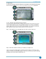
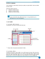
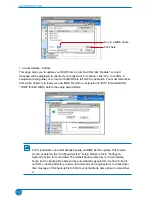
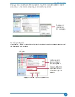
1-3 Local Update - Update
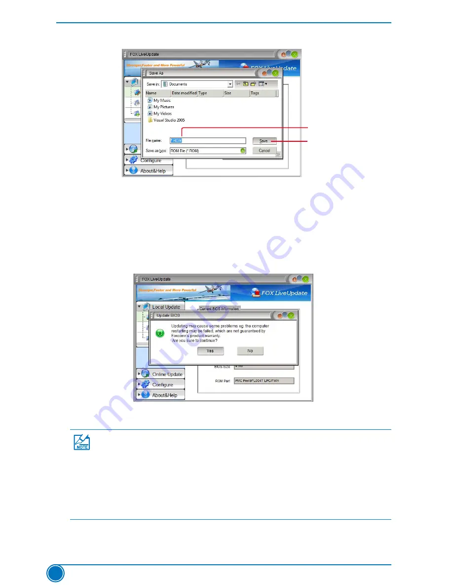
This page helps you to update your BIOS from a local file. After click “Update”, An alert 
message will be displayed to ensure if you really want to continue, click “Yes” to confirm. A 
setup wizard will guide you to load a local BIOS file to finish the operation. You must remember 
from which directory to load your new BIOS file (with an extension of ".BIN" for Award BIOS, 
".ROM" for AMI BIOS) before the setup wizard starts.
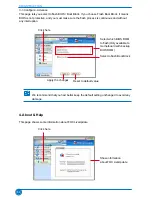
Key in a BIOS name

Click here

 
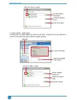
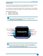
FOX LiveUpdate can automatically backup old BIOS before update. This feature 
can be enabled in the "Configure-System" setup. Please refer to "Configure-
System" section for more detail. The default backup directory is C:\LiveUpdate_
Temp, but the backup file name will be automatically generated. It is hard to find it 
out from a backup directory, and we recommend you using Explorer to check date/
time message of this backup file to find it out and write its name down to remember 
it.

Summary of Contents for H61AP Series

Page 1: ...H61AP Series Motherboard User s Manual ...

Page 2: ... can help you to use motherboard better and tells you how to avoid problems Caution indicating a potential risk of hardware damage or physical injury may exist WEEE The use of this symbol indicates that this product may not be treated as household waste By ensuring this product is disposed of correctly you will help prevent potential negative consequences for the environment and human health which...

Page 3: ...of radio disturbance characteristics of information technology equipment EN 61000 3 2 2000 Electromagnetic compatibility EMC Part 3 Limits Section 2 Limits for harmonic current emissions equipment input current 16A per phase EN 61000 3 3 A1 2001 Electromagnetic compatibility EMC Part 3 Limits Section 2 Limits of voltage fluctuations and flicker in low voltage supply systems for equipment with rate...

Page 4: ...ufacturer HON HAI PRECISION INDUSTRY COMPANY LTD Address 66 CHUNG SHAN RD TU CHENG INDUSTRIAL DISTRICT TAIPEI HSIEN TAIWAN R O C Supplementary Information This device complies with Part 15 of the FCC Rules Operation is subject to the following two conditions 1 this device may not cause harmful interference and 2 this device must accept any interference received including interference that may caus...

Page 5: ...ans in order to avoid damage to the motherboard and CPU due to high temperature Never turn on the computer if the CPU fan is not properly installed We cannot guarantee that your system can operate normally when your CPU is overclocked Normal operation depends on the overclocking capacity of your device If there is any when connecting USB audio 1394a RS232 COM IrDA or S PDIF cables to the internal ...

Page 6: ...all other Internal Connectors 14 2 5 Jumpers 18 Chapter 3 BIOS Setup Enter BIOS Setup 21 Main 22 F center 24 Smart BIOS 24 Fox Intelligent Stepping 25 CPU Configuration 26 Performance Tuning 27 Advanced 29 North Bridge 29 ME Subsystem 30 Onboard Device Configuration 31 SATA Configuration 32 Super IO Configuration 33 Trusted Computing 34 Network Stack 35 Boot 36 CSM parameters 37 Power 38 Health 40...

Page 7: ...Frequency Control Optional 53 4 Limit Setting 53 5 Voltage Page Voltage Control Optional 56 6 Fan Page Fan Control 56 4 3 FOX LiveUpdate 57 1 Local Update 57 2 Online Update 59 3 Configure 62 4 About Help 64 4 4 FOX LOGO 65 4 5 FOX DMI 66 4 6 Smart charger 66 ...

Page 8: ...ard Foxconn products are engineered to maximize computing power providing only what you need for break through performance This chapter includes the following information Product Specifications Layout Back Panel Connectors Chapter 1 Product Introduction ...

Page 9: ... Realtek 8111F Gigabit LAN chip Support 10 100 1000Mbps Audio Realtek ALC662 Audio chip High Definition Audio 2 4 5 1 channel Support for SPDIF Out Support Jack Sensing function USB Support up to 10 x USB 2 0 ports 4 rear panel ports 3 onboard USB headers supporting 6 extra ports H61AP Support up to 8 x USB 2 0 ports 2 rear panel ports 3 onboard USB headers supporting 6 extra ports H61AP S Support...

Page 10: ...onitor System voltage detection CPU System temperature detection CPU System fan speed detection CPU overheating warning CPU System fan speed control Green Function Support ACPI Advanced Configuration and Power Interface Support S3 suspend to RAM S4 suspend to disk Support Deep S4 S5 Function Support EuP function Bundled Software FOX ONE FOX LiveUpdate FOX LOGO FOX DMI Smart Charger Operating Syste...

Page 11: ...s x16 Slot 4 PCI Slots 5 Front Audio Header 6 Speaker Header 7 SPDIF_OUT Header 8 Front USB Header 9 PCH_ME_ENABLE Jumper 10 TPM Header 11 Front Panel Header 12 CIR Header 13 SATA Connectors 14 Chipset Intel H61 15 Clear CMOS Jumper 16 24 pin ATX Power Connector 17 INTR Header 18 COM2 Header 19 DDR3 DIMM Slots 20 CPU_FAN Header 21 LGA1155 CPU Socket 9 11 10 8 6 7 13 15 16 14 12 17 18 21 19 1 2 5 3...

Page 12: ...USB port supports the USB 3 0 2 0 1 1 specification Use this port for USB devices such as an USB keyboard mouse USB printer USB flash drive and etc You need to install the USB 3 0 driver in the Driver CD before using it Back panel connectors of 5 1 channel H61AP S Back panel connectors of 5 1 channel H61AP LAN Port Audio Ports VGA Port Line In Line Out Microphone USB 3 0 Ports only for H61AP S LAN...

Page 13: ...un the Realtek audio driver in CD to assign the audio out put ports for different applications of 2 4 5 1 channels or 2 4 5 7 1 channels The fundamental audio outputs are depicted in the table above LAN Type Left Active Right Link Status Description Status Description 1000M Off No Link Off No Link Green Blinking Data Activity Off 10Mb s Connection Green 100Mb s Connection Orange 1000Mb s Connectio...

Page 14: ...should be exercised during the instal lation of these modules Please refer to the motherboard layout prior to any installation and read the contents in this chapter carefully This chapter includes the following information Install the CPU and CPU Cooler Install the Memory Install an Expansion Card Install other Internal Connectors Jumpers Chapter 2 Hardware Installation ...

Page 15: ...en and thin layer of thermal grease on the surface of the CPU Do not turn on the computer if the CPU cooler is not installed otherwise overheating and damage of the CPU may occur Set the CPU host frequency in accordance with the CPU specifications It is not recommended that the system bus frequency be set beyond hardware specifications since it does not meet the standard requirements for the perip...

Page 16: ...l cover and push the CPU socket lever back to its locked position 4 Check pin one marking triangle with the pin one corner of the CPU socket align the CPU notches with the socket alignment keys and gently put the CPU onto the socket 1 Release the CPU socket lever Before installing the CPU make sure to turn off the computer and unplug the power cord from the power outlet to prevent damage to the CP...

Page 17: ...at s it 3 Check the solder side of the motherboard the push pin should be fixed as depicted in the picture 3 2 1 4 Attach the 4 wire CPU cooler connector to the CPU FAN header on the motherboard Release bolts of CPU cooler from motherboard 1 Turning the push pin bolt along with the direction of arrow counterclockwise 2 Pull the push pin straight up 3 Turning push pin clockwise to its default posit...

Page 18: ... capacity brand speed and chips be used and please select Dual channel first to achieve optimum performance Always turn off the computer and unplug the power cord from the power outlet before installing the memory to prevent hardware damage Memory modules have a foolproof design A memory module can be installed in only one direction If you are unable to insert the memory switch the direction DIMM1...

Page 19: ...he steps below to correctly install your memory modules into the sockets Step 1 Spread the clips at both ends of the memory socket Place the memory module onto the socket then put your fingers on top edge of the module and push it down firmly and seat it vertically into the memory socket Step 2 The clips at both ends of the socket will snap into place when the memory module is securely inserted 96...

Page 20: ... your computer If necessary go to BIOS Setup to make any required BIOS changes for your expansion card s 7 Install the driver provided with the expansion card in your operating system Installing and Removing a PCI Express x16 Graphics Card Installing a Graphics Card Gently insert the graphics card into the PCI Express x16 slot Make sure the graphics card is locked by the latch at the end of the PC...

Page 21: ... supply cable into the connector and make sure it is secure 4 pin ATX 12 V Power Connector PWR2 Connect the 4 pin ATX 12V power supply to PWR2 and provides power to the CPU 20 Pin Power Pin No 24 3 1 GND 12V 4 2 PWR2 PWR1 24 13 12 1 Pin Definition Pin Definition 1 3 3V 13 3 3V 2 3 3V 14 12V 3 GND 15 GND 4 5V 16 PS_ON Soft On Off 5 GND 17 GND 6 5V 18 GND 7 GND 19 GND 8 Power Good 20 NC 9 5V SB Stan...

Page 22: ...F OUT Header SPDIF_OUT The connector is used for SPDIF output Serial ATA Connectors SATA_1 2 3 4 5 6 The Serial ATA connector is used to connect with SATA Hard Disk or CD devices which support this feature The SATA_1 2 3 4 allows up to 3GB s data transfer rate the SATA_5 6 support SATA 3 0 specification and allows up to 6GB s data transfer rate A_MIC2_L A_MIC2_R A_LINE2_L SENSE_SEND SENSE1_RETURN ...

Page 23: ...3 S4 sleep state or power off mode S5 the LED is off This 2 pin connector is directional with sign Power Switch Connector PWR SW Connect to the power button on the front panel of the chassis Push this switch allows the system to be turned on and off rather than using the power supply button TPM Header TPM The TPM Trusted Platform Module provides the ability to the PC to run applications more secur...

Page 24: ...his connector supports infrared wireless trans mitting and receiving device COM Header COM2 This motherboard supports one serial RS232 COM port for legacy compatibility User must purchase another RS232 cable with a 9 pin D sub connector at one end to connect with the external RS232 device and another end with 10 pin female connector to connect with COM1 connector in the motherboard INTR GND INTRUD...

Page 25: ...Discharge problem Clear CMOS Jumper CLR_CMOS The motherboard uses CMOS RAM to store the basic hardware information such as BIOS data date time information hardware password etc Clear CMOS data is the fast way to go back to factory default when the BIOS settings were mistakenly modified The steps to clear CMOS data are 1 Turn off the computer unplug the power cord from the power outlet 2 Remove jum...

Page 26: ... AMT that allows to improve manage ment of corporate assets Set the jumper to pins 1 2 you can enable the Intel Management Engine function Set the jumper to pins 2 3 you can disable the Intel Management Engine function Enable Default 1 2 3 Disable 1 2 3 PCH_ME_ENABLE Definition Description Function 1 2 default Set Pin 1 and Pin 2 closed Enable ME function 2 3 Set Pin 2 and Pin 3 closed Disable ME ...

Page 27: ... have to run the Setup Program when the following cases occur 1 An error message appears on the screen during the system Power On Self Test POST process 2 You want to change the default CMOS settings This chapter includes the following information Enter BIOS Setup Main F Center Advanced Boot Power Health Security Save Exit Chapter 3 BIOS Setup ...

Page 28: ...items related with Green function features can be setup through this menu Health This setup enables you to read change fan speeds and displays temperatures and voltages of your CPU System Security The Administrator User password can be set up through this menu to prevent unauthorized use of your computer If you set a password the system will ask you to key in correct password before boot or access...

Page 29: ...te date from 1 to 31 Year year set up by users Use ENTER TAB or SHIFT TAB to select a field Use or to input the value System Time This item allows you to configure the desired time Use ENTER TAB or SHIFT TAB to select a field Use or to input the value The three fields of the setting are hour minute second respectively Access Level It displays your current access level If you enter system with a us...

Page 30: ...keyboard can result in system halt CPU Brand Name It displays the current CPU name Total Memory This item displays the total memory size The size is depending on how many memory mod ules are installed in your system before powering on MAC Address This item displays the onboard LAN MAC address ...

Page 31: ...ect the system BIOS there is a BIOS write protection mechanism provided to pre vent BIOS FLASH tool being improperly used to update BIOS or the vicious virus such as CHI etc rewriting BIOS setup Smart BIOS Fox Intelligent Stepping CPU Configuration Performance Tuning Press Enter to go to relative submenu Smart BIOS Smart BIOS Smart Power LED Disabled Smart Boot Menu Enabled Smart Power LED Setting...

Page 32: ...Reboot Fan OK Smart Boot Menu When PC starts it will ask you to press Del key to enter setup or press F7 key to enter smart boot menu If Disabled is selected then pressing F7 has no function This also prevents user without password trying to get into your computer through smart boot menu Fox Intelligent Stepping Spread Spectrum Enabled Spread Spectrum Settings Select Screen Click Select Item Enter...

Page 33: ...e Advanced Encryption Standard feature Intel XD Bit This item is used to enable disable the Execute Disable Bit feature Intel s Execute Disable Bit functionality can help prevent certain classes of malicious buffer overflow attacks when combined with a supporting operating system Limit CPUID Maximum This item is used to enable or disable CPUID maximum value limit configuration Set Limit CPUID Maxi...

Page 34: ...uirements must be met including CPU chipset motherboard BIOS and operation system Please refer to Intel Website for more information C A U T I O N Turbo Mode Appears only when CPU supports You can enable disable the Turbo mode North Bridge Configuration Performance Memory Profiles This item is used to select Performance memory profile Options Automatic Manual XMP Profile 1 XMP Profile 2 Automatic ...

Page 35: ... you to set the minimum RAS active time in clock cycles tWR This item allows you to select the write recovery time in clock cycles tRFC Refresh to Refresh or Refresh to Active command interval tWTR This item allows you to select a delay time in clock cycles between sending the last data from a write operation to the memory and issuing a read command tRRD This item allows you to select a delay time...

Page 36: ... Computing Network Stack Press Enter to go to its submenu North Bridge North Bridge Configuration Memory Information Total Memory 2048 MB DDR3 1333 Memory Slot1 Not Present Memory Slot2 2048 MB DDR3 1333 Memory Configuration Integrated Graphics Auto UMA Frame buffer Size 256M Initate Graphics Adapter Auto VT D Enabled IGD Multi Montior Disabled DVMT FIXED Memory 256M Keep IGD enabled based on the ...

Page 37: ...and will no longer be available to the OS Initial Graphic Adapter This item is used to select which graphics controller is used as the primary boot device VT D This item is used to enable or disable the VT d feature Intel Virtualization Technology for Directed I O VT d can help end users improve security and reliability of the systems and also improve performance of I O devices in virtualized envi...

Page 38: ...N Controller This item is used to enable or disable the onboard LAN controller Onboard LAN PXE OpROM This item is used to enable or disable onboard LAN PXE option ROM Onboard USB Controller This item is used to enable or disable the onboard USB controller Legacy USB Support This item is used to enable the support for USB devices on legacy OS If you have a USB keyboard or mouse set to enabled Enabl...

Page 39: ...your SATA ports Native IDE This configures the SATA ports to support native IDE mode AHCI The Advanced Host Controller Interface AHCI specification describes the register level interface for a Host Controller for Serial ATA The specification includes a description of the hardware software interface between system software and the host controller hardware AHCI provides more advanced features includ...

Page 40: ...disable the serial port COM Device Settings This item shows the resource assigned to the serial port Change Settings This item is used to select an optimal settings for Super IO device Parallel Port Configuration Parallel Port This item is used to enable or disable the parallel port LPT LPTE Device Settings This item shows the resource assigned to the serial port Change Settings This item is used ...

Page 41: ...Defaults F4 Save Exit ESC Right Click Exit Version 2 14 1219 Copyright C 2012 American Megatrends Inc Main Advanced Boot Power Health Security F center Save Exit TPM SUPPORT This item is used to decide whether to support TPM Trusted Platform Module device func tion Default option is Disabled If you want to support TPM first you need to install a TPM device on the motherboard and set this item to E...

Page 42: ...3 Optimized Defaults F4 Save Exit ESC Right Click Exit Version 2 14 1219 Copyright C 2012 American Megatrends Inc Main Advanced Boot Power Health Security F center Save Exit Network stack This item is used to enable disable UEFI network stack The UEFI Unified Extensible Firmware Interface Network Stack implements the TCP IP network interfaces such as SNP MNP ARP IP UDP DHCP MTFTP and TCP ...

Page 43: ...Lock key is active when your system is started The available settings are On default and Off Quiet Boot This item is used to enable disable the quiet boot Disabled Displays the normal POST messages Enabled Displays OEM customer logo instead of POST messages Fast Boot While Enabled this option allows BIOS to skip certain tests while booting this will shorten thetime needed to boot the system Interr...

Page 44: ...xit ESC Right Click Exit Version 2 14 1219 Copyright C 2012 American Megatrends Inc Main Advanced Boot Power Health Security F center Save Exit Launch CSM This item controls if CSM will be launched Boot option filter This item controls what devices system can boot to Launch PXE OpROM policy This item controls the execution of UEFI and Legacy PXE OpROM Launch Storage OpROM policy This item controls...

Page 45: ...onsible for maintaining the caches and CPU context Control starts from the processor s reset vector after the wake event S3 The S3 sleeping state is a low wake latency sleeping state where all system context is lost except system memory CPU cache and chip set context are lost in this state Hardware maintains memory context and restores some CPU and L2 configuration context Control starts from the ...

Page 46: ...able the onboard LAN to generate a wake up Resume by RTC This item is used to enable disable RTC alarm event to generate a wake up RTC is system real time clock RTC Alarm Date Days When Resume by RTC is enabled select a specific date to generate a wake up RTC Alarm Time HH MM SS When Resume by RTC is enabled select a specific time to generate a wake up Energy using Products This item is used to en...

Page 47: ...is used to enable or disable system smart fan function Default value is Disabled Case Open Warning Disabled CPU Temperature 39 C System Temperature 35 C CPU Fan Speed 3026 RPM System Fan Speed N A CPU Vcore 1 200 V DRAM Voltage 1 608 V 12V SYS 12 300 V 5V SYS 5 097 V VBAT 3 328 V CPU Warning Temperature Disabled CPU Shutdowm Temperature Disabled CPU Smart Fan Control Disabled System Smart Fan Cont...

Page 48: ...tSector Write This item is used to enable or disable protect HDD MBR from avoiding destroied by virus Secure Boot This item is used to enable or disable Secure Boot control Secure Boot is possible only if system runs in User Mode Secure Boot Mode This item is used to select Secure Boot Mode The detailed parameter submenus will appear when you select Custom Mode Security configuration Administrator...

Page 49: ...t setup utility and reset computer without saving your modifications select No or ESC to return to the main menu Restore Defaults Optimal defaults are the best settings of this motherboard Always load the Optimal defaults after updating the BIOS or after clearing the CMOS values Select this option and press Enter it will pop out a dialogue box to let you load the defaults Select Yes and then press...

Page 50: ...d contains useful software and several utility drivers that enhance the motherboard features This chapter includes the following information Install driver and utility FOX ONE FOX LiveUpdate FOX LOGO FOX DMI Smart Charger Chapter 4 CD Instruction ...

Page 51: ...to install all the drivers for your system You must click Intel Chipset Driver to install it first After that you can click One Click Setup and then choose the items you want to install or you can click on each individual driver to install it manually Choose the items you want to Install Visit Foxconn s Website Show Utilities Show Drivers View the User s Manual Manual Installation Step by Step Aut...

Page 52: ...CD INSTRUCTION 45 Click here 2 Utility Use these options to install additional software programs And click User s manual button to view the product manual ...

Page 53: ... Stepping will require you to calibrate the CPU s loading Click OK to proceed and start the Utility F I S is a feature of FOX ONE which can automatically adjust your CPU clock based on your current system loading Depending on hardware support voltage monitoring and Fox Intelligent Stepping features are optional and only supported in some models If the option is selectable it also means the feature...

Page 54: ...mation bar i e Simple Mode as depicted below you can drag this bar to any place on your screen to help you monitoring system status Skin Button There are more choices of FOX ONE screen panels Click this button you can select your favorite skin FOX ONE Panel Click here to go back to FOX ONE full screen Click here will drop the FOX ONE to Windows system tray Exit FOX ONE Show CPU Information Toolbar...

Page 55: ...ur screen Homepage Click this button to visit Foxconn motherboard website http www foxconnchannel com Configuration 1 Monitor interval ms This is to define the interval of different messages of system settings which are to be displayed on Simple Mode screen Minimum value is 1 second Apply the changes Click the new skin picture to select the new skin Cancel the changes ...

Page 56: ...ply different loadings to your CPU record PWM IC voltage together with the CPU clock running at these loadings so it can define and estimate within a particular range of system loading what the CPU clock should be Step 1 Click Calibration icon a message pops out to ask for continue Select Yes Step 2 After data is collected it will ask you to restart your computer now Later on when the FOX ONE prog...

Page 57: ...your CPU clock Auto Click this button to let FOX ONE check the highest CPU clock you can use System will raise the CPU clock step by step until it hangs you can then push the RESET button on your PC panel to restart the system When system restarts run FOX ONE again it will display a recom mended highest CPU clock for you click Yes to apply it Press Auto button to let FOX ONE check the highest CPU ...

Page 58: ...ntinue You can see the system is raising CPU clock until the system hangs Push RESET button on the front panel of your system to restart the computer Run FOX ONE program again it will inform you the previous test found that 255MHz is the recommended CPU clock for your system Click Yes to apply it to your system ...

Page 59: ...ck will be driven to run at its maximum speed While in Energy Saving CPU will lower down its speed to a minimum The four benchmarks Power Gaming Data Mining Office and Energy Saving the references of their system loading were calculated and defined in the FIS Calibration option of Configuration menu Select Auto CPU will automatically adjust its clock according to current system loading Now your sy...

Page 60: ...t CPU high limit temperature and enable the alert function Go to Freq page Close this page Reset the changes Apply the changes Select the option you want to set Adjust by manual Go to Limit Setting page Set high limit by dragging the lever Show current CPU temperature value Enable alert function when the CPU temperature is higher than high limit value Show current high limit value of the CPU tempe...

Page 61: ...le the alert function Set high limit by dragging the lever Show current system temperature value Enable alert function when the system temperature is higher than high limit value Show current high limit value of system temperature Set low limit rpm by dragging the lever Show current CPU fan rpm value Enable alert function when the CPU fan runs slower than the low limit rpm value Show current low l...

Page 62: ...e the alert function Set low limit rpm by dragging the lever Show current FAN1 fan rpm value Enable alert function when the FAN1 fan runs slower than low limit rpm value Show current low limit rpm value of FAN1 fan Set low limit rpm by dragging the lever Show current system fan rpm value Enable alert function when the system fan runs slower than low limit rpm value Show current low limit rpm value...

Page 63: ...step and North Bridge is 0 04V step 6 Fan Page Fan Control This page lets you enable Smart Fan function or set the fan speed by manual When Smart Fan is selected you must use a 4 pin CPU cooler in your system Go to Voltage page Select the option you want to set Adjust by manual Reset the changes Apply the changes Go to Fan page Set fan speed by dragging the lever Enable or disable smart fan functi...

Page 64: ... physical motherboard for detail 1 2 Local Update Backup This page can backup your system BIOS You can click Backup and key in a file name then click Save to finish the backup operation The extension of this backup file is BIN for Award BIOS and ROM for AMI BIOS Make sure you can remember the file name together with the directory which it is stored prevented that you may need them to recover your ...

Page 65: ...sion of BIN for Award BIOS ROM for AMI BIOS before the setup wizard starts Key in a BIOS name Click here FOX LiveUpdate can automatically backup old BIOS before update This feature can be enabled in the Configure System setup Please refer to Configure System section for more detail The default backup directory is C LiveUpdate_ Temp but the backup file name will be automatically generated It is har...

Page 66: ...e operation 2 2 Online Update Update Driver This page lets you update your system drivers from Internet Click Start it will search the new drivers from Internet Then follow the wizard to finish the update operation Click here Current information Search new BIOS from Internet Browse detailed information Update BIOS Close the window Select BIOS to update Click here Current information Search new dri...

Page 67: ...ties from Internet Then follow the wizard to finish the update operation Browse detailed information Install the selected driver Close the window Select the driver to update Click here Current information Search new utilities from Internet Browse detailed information Install the selected utility Close the window Select the utility to update ...

Page 68: ...t it will search all new BIOS drivers utilities from Internet Then follow the wizard to finish the update operation Click here Current information Search all new BIOS drivers utilities from Internet Browse detailed BIOS information Close the window Browse detailed driver information Browse detailed utility information ...

Page 69: ...ing from Internet and if any qualified item found it will pop out a message on the task bar to inform you to do the next step Double click on the icon as show below you can see the detailed information Double click here Apply the changes Reset to default value Click here Set auto search options Select search which kind of versions Set auto search the latest FOX LiveUpdate ...

Page 70: ...rsion 3 2 Configure System This page lets you set the backup BIOS location and determine if the FOX LiveUpdate can auto run when the system starts up Prompt you to install the new FOX LiveUpdate Click here Set the location of download files or auto backup BIOS Determine if the FOX LiveUpdate can auto run when the system starts up Apply the changes Reset to default value ...

Page 71: ...ntinuous and without any interruption 4 About Help This page shows some information about FOX LiveUpdate Click here Select which BIOS ROM to flash Only available to motherboard with backup BIOS ROM Apply the changes Reset to default value Select to flash Boot Block Click here Show information about FOX LiveUpdate We recommend that you had better keep the default setting unchanged to avoid any dama...

Page 72: ...nable the Quiet Boot setting in BIOS Supporting Operating Systems Windows 8 32 bit and 64 bit Windows 7 32 bit and 64 bit Windows XP 32 bit and 64 bit When you change Logo or delete current Logo the system will flash BIOS file automatically During this time please DO NOT shut down the application and the system or the motherboard will be damaged seriously C A U T I O N Minimize Exit Website About ...

Page 73: ...oard if there is any problem occurred Supporting Operating Systems Windows 8 32 bit and 64 bit Windows 7 32 bit and 64 bit Windows XP 32 bit and 64 bit Please operate this utility as the comments shows Click here to select the DMI Data format you need Click here to select the type you want to view 4 6 Smart charger Smart Charger is used for iPad recharging and when connected an icon will appear on...

Reviews: