background image

Statement:

This manual is the intellectual property of Foxconn, Inc. Although the
information in this manual may be changed or modified at any time,
Foxconn does not obligate itself to inform the user of these changes.

Trademark:

All trademarks are the property of their respective owners.

Version:

User

s Manual V1.0 for P35AX Series motherboard.

Symbol description:

Note:

 refers to important information that can help you to use motherboard

              better.

Attention:

 indicates that it may damage hardware or cause data  loss,

             and tells you how to avoid such problems.

Warning: 

means that a potential risk of property damage or physical

injury exists.

More information:

If you want more information about our products, please visit Foxconn

s

website: 


http://www.foxconnchannel.com


WEEE: 

The use of the symbol indicates that this product may not be

treated as household waste. By ensuring this product is disposed of
correctly, you will help prevent potential negative consequences for the
environment and human health, which could otherwise be caused by
inappropriate waste handling of this product. For more detailed informa-
tion about recycling of this product, please contact your local city office,
your household waste disposal service or the shop where you pur-
chased the product.

PDF 

文件使用

 "pdfFactory" 

试用版本创建


www.fineprint.com.cn

Summary of Contents for P35AX Series

Page 1: ...to avoid such problems Warning means that a potential risk of property damage or physical injury exists More information If you want more information about our products please visit Foxconn s website http www foxconnchannel com WEEE The use of the symbol indicates that this product may not be treated as household waste By ensuring this product is disposed of correctly you will help prevent potenti...

Page 2: ... characteristics of information technology equipment þ EN 61000 3 2 2000 Electromagnetic compatibility EMC Part 3 Limits Section 2 Limits for harmonic current emissions equipment input current 16A per phase þ EN 61000 3 3 A1 2001 Electromagnetic compatibility EMC Part 3 Limits Section 2 Limits of voltage fluctuations and flicker in low voltage supply systems for equipment with rated current 16A þ ...

Page 3: ...ufacturer HON HAI PRECISION INDUSTRY COMPANY LTD Address 66 CHUNG SHAN RD TU CHENG INDUSTRIAL DISTRICT TAIPEI HSIEN TAIWAN R O C SupplementaryInformation This device complies with Part 15 of the FCC Rules Operation is subject to the follow ing two conditions 1 this device may not cause harmful interference and 2 this device must accept any interference received including interference that may caus...

Page 4: ...es 26 5 PCI PnP Resource Management 27 6 Power Management Features 28 7 Hardware Health Configure 29 8 BIOS Security Features 29 9 Load Optimal Defaults 30 10 Load FailSafe Defaults 30 11 Save Changes and Exit 30 12 Discard Changes and Exit 30 2 FOX ONE 32 FOX LiveUpdate 35 FOX LOGO 37 FOX DMI 38 3 Chapter 2 BIOS Description Chapter 1 1 Chapter 3 Directions for Bundled Software Main Features ...

Page 5: ...system or memory module Since BIOS programs are upgrated from time to time the BIOS description in this manual is just for reference We do not guarantee that the content of this manual will remain consistent with the actual BIOS version at any given time in the future Attention Attention Attention Please visit the Foxconn global English website http www foxconnchannel com to download the latest BI...

Page 6: ......

Page 7: ...s and offers superior performance reliability and quality at a reason able price This motherboard adopts the advanced Intel P35 ICH9 chipset providing users a computer platform with a high integration compatibility performance price ratio This chapter includes the following information v Specifications v Jumpers 1 1 ...

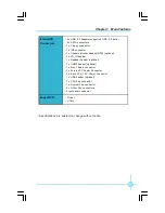
Page 8: ...Intel High Definition Audio 4 x SATA 300MB s devices 2 x Ultra DMA 133 100 66 devices 1 x eSATA 300MB s device LGA775 socket for Intel CoreTM 2 Quad CoreTM 2 Extreme CoreTM 2 Duo Pentium Dual Core E2xxx Celeron 4xx Pentium 4 Extreme Edition Pentium D Pentium 4 processors Supports Hyper Threading Technology Storage 2 x 240 pin DIMM slots Supports Dual Channel DDR2 800 667 Supports up to 4GB 1333 10...

Page 9: ...ector 1 x Chassis intruder header INTR optional 1 x CD_IN header 1 x Speaker header optional 1 x COM2 header optional 1 x Front Audio connector 1 x 24 pin ATX Power Connector 1 x 8 pin ATX_12V Power Connector 1 x IrDA header optional 1 x CPU Fan connector 1 x System Fan connector 2 x Other Fan connectors Front panel connector Internal I O Connectors Support CD Driver Utility ...

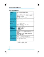
Page 10: ... CoreTM 2 Duo Pentium Dual Core E2xxx Celeron 4xx Pentium 4 Extreme Edition Pentium D Pentium 4 处理器 支持 Hyper Threading 技术 ATX 结构 305mm x 208mm 尺 寸 中央处理器 芯片组 内 存 LAN 扩展槽 2 个 PCI Express x16 插槽 1 个 PCI Express x1 插槽 3 个 PCI 插槽 音 频 存 储 4 个 SATA 300MB s 设备 2 个 Ultra DMA 133 100 66 设备 1 个 eSATA 300MB s 设备 Realtek 6 声道音频编解码器 Realtek 8 声道音频 编解码器 支持 S PDIF 输出 Jack Sensing 功能 Intel High Definition Audio 系统...

Page 11: ...ker 接头 选配 1 个 COM2 接头 选配 1 个 前置音频接头 1 个 24 针ATX 电源接口 1 个 8 针 ATX_12V 电源接口 1 个 红外线通讯接头 选配 1 个 CPU 风扇接头 1 个 系统风扇接头 2 个 其它风扇接头 FAN1 FAN2 前端面板接头 内置连接器 规格若有任何更改 恕不另行通知 实用程序光盘 驱动程序 应用程序 后面板I O 1 个 PS 2 鼠标接口 1 个 PS 2 键盘接口 1 个 串行接口 COM1 1 个 并行接口 1 个 同轴 S PDIF 数码音频输出接口 1 个 eSATA 接口 4 个 USB 2 0 接口 1 个 RJ45 网络接口 6 8声道音频接口 ...

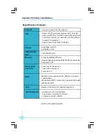
Page 12: ... Kanal Audio CODEC Realtek 8 Kanal Audio CODEC Unterstützt S PDIF Ausgang Anschlusserkennung Intel High Definition Audio 4 x SATA Geräte 300 MB s 2 Ultra DMA 133 100 66 Geräte 1 x eSATA 300MB s Gerät LGA775 Sockel für Intel _ CoreTM 2 Quad CoreTM 2 Extreme CoreTM 2 Duo Pentium _Dual Core E2xxx Celeron _4xx Pentium _4 Extreme Edition Pentium _D Pentium _4 Prozessoren Unterstützt Hyper Threading Tec...

Page 13: ...nal 1 x Front Audio Anschluss 1 x ATX Power 24 polig Anschluss 1 x ATX_12V Power 8 polig Anschluss 1 x IrDA Anschluss optional 1 x CPU Lüfter Anschluss 1 x Systemlüfter Anschluss 2 x Anderer Lüfter Anschlüsse Frontbedienfeld Anschluss Interne I O Anschlüsse Support CD Treibe Dienstprogramme I O Anschlüsse an der Rückseite 1 x PS 2 Mausanschluss 1 x PS 2 Tastaturanschluss 1 x Seriellanschluss COM1 ...

Page 14: ...les Audio CODEC Realtek 8canales Audio CODEC Compatible salida S PDIF sensible a conexión sonido Intel de Alta Definición 4 x dispositivos SATA 300MB s 2 x dispositivos Ultra DMA 133 100 66 1 x dispositivo eSATA 300MB s Conector LGA775 para procesadores Intel CoreTM 2 Quad CoreTM 2 Extreme CoreTM 2 Duo Pentium Dual Core E2xxx Celeron 4xx Pentium 4 Extreme Edition Pentium 4 Pentium D Compatible con...

Page 15: ...l 1 x Conector de Audio frontal 1 x Conector de 24 pin ATX Power 1 x Conector de 8 pin ATX_12V Power 1 x Cabecera de IrDA opcional 1 x Conector de Ventilador de CPU 1 x Conector de Ventilador Sistema 2 x Conector de Otro ventilador Conector de panel frontal Conectores internos de E S CD de soporte Controlador Utilidades Panel de E S trasero 1 x Puerto de ratón PS 2 1 x Puerto de teclado PS 2 1 x P...

Page 16: ...Realtek com 8 canais codec de áudio Suporta saída S PDIF função Jack Sensing áudio de alta definição da Intel 4 dispositivos SATA de 300 MB s 2 dispositivos Ultra DMA 133 100 66 1 dispositivo eSATA 300MB s Socket LGA775 para processadores Intel _CoreTM 2 Quad CoreTM 2 Duo CoreTM 2 Extreme Pentium _Dual Core E2xxx Celeron _4xx Pentium _4 Extreme Edition Pentium _D Pentium _4 Suporta a tecnologia Hy...

Page 17: ...ector Áudio frontal 1 x Conector de alimentação ATX de 24 pinos 1 x Conector de alimentação ATX de 8 pinos e de 12 V 1 x Conector IrDA opcional 1 x Conector da ventoinha da CPU 1 x Conector ventoinha do sistema 2 x Conectores Outra ventoinha Conector de painel frontal Conectores internos de entrada saída CD de suporte Controlador Utilitários Entrada Saída pelo painel traseiro 1 x Porta para rato P...

Page 18: ...o CODEC Realtek 8 canali audio CODEC Supporto output S PDIF funzione di rilevamento connettori Intel High Definition Audio 4 dispositivi SATA 300MB s 2 dispositivi Ultra DMA 133 100 66 1 dispositivo eSATA 300MB s Socket LGA775 per processori Intel CoreTM 2 Quad CoreTM 2 Extreme CoreTM 2 Duo Pentium Dual Core E2xxx Celeron 4xx Pentium 4 Extreme Edition Pentium D Pentium 4 Supporto tecnologia Hyper ...

Page 19: ...OM2 optional 1 x Connettore Audio frontale 1 x Connettore potenza ATX 24 pin 1 x Connettore potenza ATX_12V 8 pin 1 x Connettore IrDA optional 1 x Connettore ventolina CPU 1 x Connettore ventolina di sistema 2 x Connettori altra ventolina Connettore pannello frontale Connettori I O interni CD di supporto Driver Utilità Pannello posteriore I O 1 x Porta mouse PS 2 1 x Porta tastiera PS 2 1 x Porta ...

Page 20: ...ДЕК Поддержка Выход S PDIF функция определения разъема поддержка технологии Intel High Definition Audio 4 устройства с интерфейсом SATA и скоростью передачи данных 300 Мб с 2 устройства с интерфейсом Ultra DMA 133 100 66 1 устройствo eSATA 300 Мб с Гнездо LGA775 для процессоров Intel _ CoreTM 2 Quad CoreTM 2 Extreme CoreTM 2 Duo Pentium _Dual Core E2xxx Celeron _4xx Pentium _4 Extreme Edition Pent...

Page 21: ... 1 Передний звуковой разъем 1 Разъем 24 контактный ATX 1 Разъем 8 контактый ATX_12V 1 ИК порт дополнительный 1 Разъем Вентилятор процессора 1 Разъем системный вентилятор 2 Разъемы другой вентилятор Передняя панель разъем Встроенные входы и выходы Поддержка компакт дисков Драйвер Служебная программа Входы и выходы на задней панели 1 Порт мыши PS 2 1 Порт Клавиатура PS 2 1 Последовательный порт COM1...

Page 22: ...00 667 Ÿ ﺇﻟﻰ ﻴﺼل ﺩﻋﻡ 4 ﺒﺎﻴﺕ ﺠﻴﺠﺎ ﺍﻟﺘﻭﺴﻌﺔ ﻓﺘﺤﺎﺕ Ÿ ﻋﺩﺩ 2 ﻓﺘﺢ ﺓ PCI Express x16 Ÿ ﻋﺩﺩ 1 ﻓﺘﺤﺔ PCI Express x1 Ÿ ﻋﺩﺩ 3 ﻓﺘﺤﺎﺕ PCI ﺍﻟﺼﻭﺕ Ÿ ﺒﺘﻘﻨﻴﺔ ﻗﻨﻭﺍﺕ ﺒﺴﺕ ﺼﻭﺘﻲ ﺘﺭﻤﻴﺯ Realtek ﺘﺭﻤﻴﺯ ﺼﻭﺘﻲ ﺒﺜﻤﺎﻥ ﻗﻨﻭﺍﺕ ﺒﺘﻘﻨﻴﺔ Realtek Ÿ ﺨﺭﺝ ﺩﻋﻡ S PDIF ﺘﻘﻨﻴﺔ ﺍﻟﻤﻘﺒﺱ ﺍﺴﺘﺸﻌﺎﺭ ﻭﻅﻴﻔﺔ Intel High Definition Audio ﺍﻟﻤﺤﻠﻴﺔ ﺍﻻﺘﺼﺎل ﺸﺒﻜﺔ Ÿ Realtek Gigabit LAN Realtek 10 100 Mb s LAN ﺍﻟﺘﺨﺯﻴﻥ Ÿ ﻋﺩﺩ 2 ﺃﺠﻬﺯﺓ Ultra DMA 133 100 66 Ÿ ﻋﺩﺩ 4 ﺃﺠﻬﺯﺓ ...

Page 23: ... ﻟﻠﻬﻴﻜل INTR ﺍﺨﺘﻴﺎﺭﻱ Ÿ ﻋﺩﺩ 1 ﺘﻭﺼﻴل ﻁﺭﻑ CD_IN Ÿ ﻋﺩﺩ 1 ﺍﻟﺴﻤﺎﻋﺔ ﺘﻭﺼﻴل ﻁﺭﻑ ﺍﺨﺘﻴﺎﺭﻱ Ÿ ﻋﺩﺩ 1 ﺘﻭﺼﻴل ﻁﺭﻑ COM2 ﺍﺨﺘﻴﺎﺭﻱ Ÿ ﺍﻷﻤﺎﻤﻲ ﺍﻟﺼﻭﺕ ﻤﻭﺼل Ÿ ﻋﺩﺩ 1 ﻁﺎﻗﺔ ﻤﻭﺼل ATX ﺀ 24 ﺩﺒﻭﺱ Ÿ ﻋﺩﺩ 1 ﻁﺎﻗﺔ ﻤﻭﺼل ATX_12V 8 ﺩﺒﺎﺒﻴﺱ Ÿ ﻋﺩﺩ 1 ﺘﻭﺼﻴل ﻁﺭﻑ IrDA ﺍﺨﺘﻴﺎﺭﻱ Ÿ ﻋﺩﺩ 1 ﺍﻟﻤﺭﻜﺯﻴﺔ ﺍﻟﻤﻌﺎﻟﺠﺔ ﻟﻭﺤﺩﺓ ﻤﺭﻭﺤﺔ Ÿ ﻋﺩﺩ 1 ﺍﻟﻨﻅﺎﻡ ﻟﻤﺭﻭﺤﺔ ﻤﻭﺼل Ÿ ﻋﺩﺩ 2 ﺘﻭﺼﻴل ﻤﻨﺎﻓﺫ أﺧﺮى ﻣﺮوﺣﺔ Ÿ ﺍﻷﻤﺎﻤﻴﺔ ﺍﻟﻠﻭﺤﺔ ﻤﻭﺼل ﺍﻟﻤﺩﻡ ﺍﻟﻘﺭﺹ ﺩﻋﻡ Ÿ ﺍﻟﺘﺸﻐﻴل ﺒﺭﻨﺎﻤﺞ Ÿ ﺍﻷﺩﻭﺍﺕ Ÿ ﻤﺴﺒﻕ ﺇﺨﻁﺎﺭ...

Page 24: ...lug the power cord from the power supply 2 Move the jumper cap from pins 2 3 default to pins 1 2 Keep the cap on pins 1 2 for several seconds then move the cap back to pins 2 3 3 Plug the power cord and turn on the computer This section explains how to setup jumpers You should read the following content carefully prior to modifying any jumper settings The jumpers on the motherboard pin 1 can be id...

Page 25: ...during the system POST process 2 You want to change the default CMOS settings This chapter includes the following information v Enter BIOS Setup v Main Menu v Standard BIOS Features v Fox Central Control Unit v Boot Configuration Features v Advanced BIOS Features v PCI PNP Resource Management v Power Management Features v Hardware Health Configure v BIOS Security Features v Load Optimal Defaults v...

Page 26: ... correlative information of the the items will appear at the bottom and execute the sub menu by pressing Enter Main Menu The items in the main menu are explained as below 1 Standard BIOS Features The basic system configuration can be set up through this menu 2 Fox Central Control Unit The special features can be set up by this menu 3 Boot Configuration Features This menu is used for Boot setting 4...

Page 27: ...d Exit Save CMOS value settings to CMOS and exit setup 12 Discad Changes and Exit Abandon all CMOS value changes and exit setup 1 Standard BIOS Features Standard BIOS Features Menu AMIBIOS Processor System Memory These items show the information of the AMIBIOS system processor and the system memory detemined by POST of the BIOS 1 1 System Time System Date This item allows you to set up the desired...

Page 28: ...llows you to select the kind of FDD to be installed including none 360K 51 4 in 1 2M 51 4in 720K 31 2 in 1 44M 31 2 in and 2 88 M 31 2 in 2 Fox Central Control Unit Fox central control Unit Menu Overclock Options Menu 2 1 Smart power LED Enable this function the smart LED can show the system status of POST process 2 2 Overclock Options Fox Ratio Select Use it to enabled or disabled the Fox Ratio s...

Page 29: ...d to set the PCIE spread spectrum functions NOTE The Spread Spectrum function can influence the EMI degree Memory Remap Feature This item is used to set the memory remap feature DRAM Frequency This item is used to adjust the DRAM frequency Configure DRAM Timing by SPD This item is used to configure DRAM timing by SPD Memory Hole This item is used to set the memory hole Voltage Options Menu 2 3 Vol...

Page 30: ...led by operating system Disabled default CPU speed C1E Support This item is used to set the C1E support It should be enabled in order to enable or disable the Enhanced Halt State Hardware Prefetcher This item is used to enable or disable the hardware prefetcher function Adjacent Cache Line prefetch This item is used to enable or disable the Adjacent Cache Line prefetch function 2 4 CPU Configurati...

Page 31: ...Current 3 4 Interrupt 19 Capture This item when enabled allows option ROMs to trap interrupt 19 3 5 Wait For F1 If Error This item is used to set whether to wait for F1 key to be pressed if error occurs Enabling this option causes the system to pause the POST if it en counters an error and wait for user to press the F1 key before resuming Intel R Virtualization Tech This item is used to enable or ...

Page 32: ... for the configuration of onboard devices such as USB controller Graphic Adapter HDA controller PEG port and so on 4 Advanced BIOS Features 3 6 Hit DEL Message Display This item is used to set whether to show the information about press DEL to run BIOS setup in POST 3 7 Boot Device Priority This option is used to select the priority for devices After pressing Enter you can select the devices using...

Page 33: ...play operating system 5 3 PCI Latency Timer This item is used to set the PCI latency timer The value is in units of PCI clock for PCI device latency timer register 5 4 Allocate IRQ to PCI VGA This item is used to set if allocate IRQ to PCI VGA Yes Assigns IRQ to PCI VGA card if card requests IRQ No Does not assign IRQ to PCI VGA card even if card requests an IRQ 5 5 Palette Snooping This item is u...

Page 34: ...abling APIC mode will expand available IRQs resources 6 5 USB Device Wakeup From S3 S4 This item allows you to enable or disable the USB device wakeup from S3 S4 6 6 Restore on AC Power Loss This item is used to set which state the PC will take with when it resumes after an AC power loss 6 7 High performance Event Timer This item is used to enable or disable the High Performance Event Timer HPET 6...

Page 35: ... Menu 7 1 Fan 1 Mode Setting This item is used to set the fan 1 configuration mode 7 2 Temperature 1 Limit of Hig Sec Thi Low These items are used to set the fan temperature limit 7 3 Fan 1 Highest Second Third Fourth Lowest Setting These items are used to set the fan speed CPU Temperature System Temperature CPU Fan Speed System Fan Speed Vcore 1 8V SUS 1 2V CORE 5V 12V 3 3V VCC VSB VBAT These ite...

Page 36: ...formance parameters of system to improve the performances of system components You can select Y or N and then press Enter to load or not load the optimized defaults 11 Save Changes and Exit 12 Discard Changes and Exit If you select this option and press Enter the following message will appear in the center of the screen Quit Without Saving Y N Y Press Y to exit CMOS without saving your modificatio...

Page 37: ...Chapter 4 Driver CD Introduction 31 This chapter will introduce how to use bundled software This chapter provides the following information v FOX ONE v FOX LiveUpdate v FOX LOGO v FOX DMI 3 3 Chapter ...

Page 38: ...ng Systems Windows 2000 Windows XP 32 bit and 64 bit Windows 2003 32 bit and 64 bit Windows Vista 32 bit and 64 bit Using FOX ONE 1 Main Page Alert Lamp When the system is in healthy status the alert lamp color is green And if the system is in abnormal status the alert lamp color will turn red Switch Button Click this button it will simplify the interface to HW monitor information bar as the below...

Page 39: ...ovides F I S calibration function which will re calibrate the CPU s loading F I S calibration function is optional Homepage Click this button to visit FOXCONN motherboard website 2 CPU Page CPU Control This page is used to select and run the CPU frequency to determine the current performance level of the system You can adjust manually or select Auto Overclock Otherwise it also provides FOX Intelli...

Page 40: ...re used to set low limit rpm And all of them have alert function 5 Voltage Page Voltage Control This page allows you to set CPU memory and North Bridge voltage manually Go to Limit Setting page Set high limit by dragging the lever Show current CPU temperature value Enable alert function when the CPU temperature is higher than high limit value Show current high limit value of CPU temperature Go to ...

Page 41: ... Apply the changes Go to Fan page Set fan speed by dragging the lever Enable or disable smart fan function Apply the changes Reset the changes FOX LiveUpdate FOX LiveUpdate is a useful utility to backup and update the system BIOS online or locally Drivers and utilities are aslo can be updated online Supported Operating Systems Windows 2000 Windows XP 32 bit and 64 bit Windows 2003 32 bit and 64 bi...

Page 42: ... lets you update your system BIOS Drivers Utilities and all of them from Internet Click start it will search the new BIOS Drivers and Utilities from Internet Then follow the wizard to finish the update operation Exit Toolbar Minimum Show current BIOS information Link to website Click here Current information Search new BIOS Drivers and Utilities from Internet 3 Configure Option provides auto searc...

Page 43: ...kup BIOS location and change different skin of the utility Advance helps you to flash BIOS Boot Block and clear CMOS we recommend that you keep the default setting unchanged to avoid damagement FOX LOGO FOX LOGO is a simple and useful utility to backup change and delete the boot Logo The boot Logo is the image that appears on screen during the Power On Self Tests POST Supported Operating Systems W...

Page 44: ...Windows Vista 32 bit and 64 bit Using FOX DMI Click here to select theDMI Data format you need Click here to select the type you want to view Please operate this utility as the comments shows Main Page Minimize Exit Website About Backup Change D elete Main screen Warning When you change Logo or delete current Logo the system will flash BIOS file automatically During this time please DO NOT shut do...

Reviews: