15
5.2 Module PCB Layout
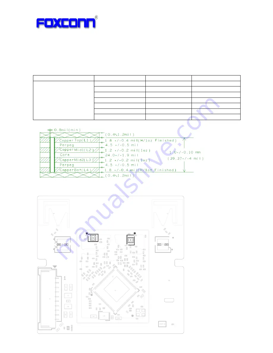
5.2.1 PCB
Stack-up
PCB
Thickness
:
1.0mm+/
‐
0.1mm
PCB
Layers
:
4
Layers
Material:
HF
FR4,
Tg150
PCB Thickness
Layers
Thickness
Tolerance
Layer 1
1.8mil
±0.4mil
Perpeg 4.5mil
±0.5mil
Layer 2
1.2mil
±0.2mil
Perpeg 24.0mil
±1.9mil
Layer 3
1.2mil
±0.2mil
Perpeg 4.5mil
±0.5mil
1.0mm±0.1mm
Layer 4
1.8mil
±0.4mil
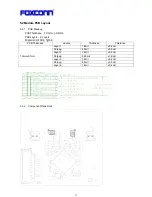
5.2.2 Component
Placement
Summary of Contents for QCA9375
Page 3: ...3 1 Revision History Date Document revision Change History 2013 5 24 1 0 Initial release...
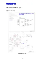
Page 13: ...13 5 Schematic and PCB Layout 5 1 Module Schematic Block Diagram Mckinley BB MAC Transceiver...
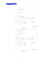
Page 14: ...14 RF Chain 0 RF Chain 1...
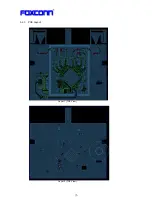
Page 16: ...16 5 2 3 PCB Layout Layer 1 TOP View Layer 2 TOP View...
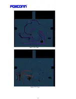
Page 17: ...17 Layer 3 TOP View Layer 4 TOP View...
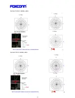
Page 19: ...19 Antenna 0 2 4GHz radiation pattern Antenna 0 5GHz radiation pattern...
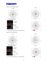
Page 20: ...20 Antenna 1 2 4GHz radiation pattern Antenna 1 5GHz radiation pattern...
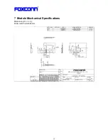
Page 21: ...21 7 Module Mechanical Specifications Dimension W x L x H 40 0mmx37 5mmx5 45mm...
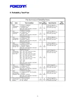
Page 23: ...23 9 Reliability Test Plan...
Page 24: ...24...
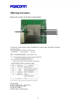
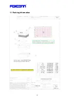
Page 26: ...26 11 Packing Information...
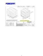
Page 27: ...27...

