6
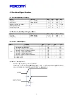
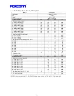
4 Electrical Specification
4.1 Absolute Maximum Rating
Symbol
Condition
Min.
Typ.
Max
Unit
VCC_3.3V
Respect to GND
-0.3
3.3
3.6
V
CHIP_PWD_L
Respect to GND
-0.3
3.3
3.6
V
Max Ripple on Supplied Voltage
3.3V
165
mVpp
Operating Temperature
--
-10
25
75
℃
Storage Temperature
--
-40
25
85
℃
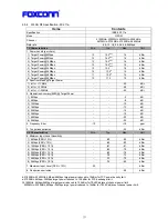
4.2 Recommended Operating Condition
Symbol
Condition
Min.
Typ.
Max
Unit
VCC_3.3V
Respect to GND
3.14
3.3
3.46
V
CHIP_PWD_L
Respect to GND
-0.3
3.3
3.46
V
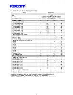
4.3 Power Consumption
Symbol
Condition
Min
Typ.
Max
Unit
Supply voltage
3.0
3.3
3.6 V
Tx Current(1Mbps/16dBm,MIMO)
--
465
--
mA
Tx Current(11g: 54Mbps/14.5dBm,MIMO)
--
400
--
mA
Tx Current(11gn: MCS15/13dBm/HT20,MIMO) --
380
--
mA
Tx Current(11a: 6Mbps/15dBm,MIMO)
--
630
--
mA
Tx Current(11a: 54Mbps/12dBm,MIMO)
--
490
--
mA
Tx Current(11an: MCS15/10dBm/HT40,MIMO) --
425
--
mA
Rx Current: 2.4GHz
--
120
--
mA
3.3V
Rx Current: 5GHz
--
130
--
mA
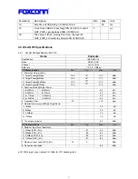
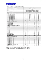
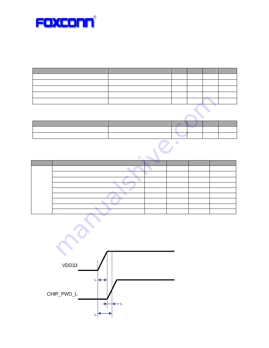
4.4 Power Up Sequence
Power
up
(reset)
timing
is
shown
as
below:
When
host
processor
controls
the
CHIP_PWD_L
reset
pin,
then
all
power
supplies
should
be
stable
for
minimum
of
5
μ
s
before
CHIP_PWD_L
is
de
‐
asserted.
Summary of Contents for QCA9375
Page 3: ...3 1 Revision History Date Document revision Change History 2013 5 24 1 0 Initial release...
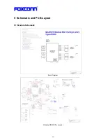
Page 13: ...13 5 Schematic and PCB Layout 5 1 Module Schematic Block Diagram Mckinley BB MAC Transceiver...
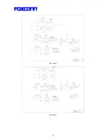
Page 14: ...14 RF Chain 0 RF Chain 1...
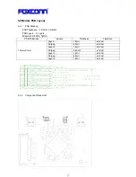
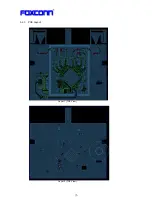
Page 16: ...16 5 2 3 PCB Layout Layer 1 TOP View Layer 2 TOP View...
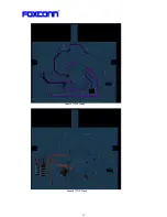
Page 17: ...17 Layer 3 TOP View Layer 4 TOP View...
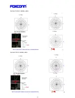
Page 19: ...19 Antenna 0 2 4GHz radiation pattern Antenna 0 5GHz radiation pattern...
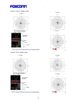
Page 20: ...20 Antenna 1 2 4GHz radiation pattern Antenna 1 5GHz radiation pattern...
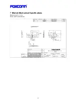
Page 21: ...21 7 Module Mechanical Specifications Dimension W x L x H 40 0mmx37 5mmx5 45mm...
Page 23: ...23 9 Reliability Test Plan...
Page 24: ...24...
Page 26: ...26 11 Packing Information...
Page 27: ...27...

