background image


WBU063-VZ 

10 


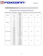
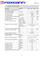
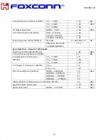
In-band Spurious Emission (TRM13) 

f-f

0

= 1MHz 

≤ -26 

dB 

f-f

0

= 2MHz 

≤ -20 

dBm 

f-f

0

≥ 3MHz 

≤ -40 

TX Output Spectrum –  

30MHz – 1GHz 

≤ -36 

dBm 

Out of Band Spurious Emission 

1GHz -12.75GHz 

≤ -30 


5.15GHz -5.35GHz 

≤ -47 

5.725GHz-5.825GHz 

≤ -47 

Enhanced power control (TRM14) 

Step Size 

2 ≤ Step Size ≤ 8 

dB 


Difference. Btw. GFSK, 
π/4 DQPSK,&8DPSK 

≤ 10 

Basic Data Rate – Receiver Performance 
Sensitivity at 0.1% BER (RCV01-02) 

≤ -81 

dBm 

C/I Co-Channel interference (RCV03) 

≤ 11 

dB 

C/I Adjacent CH interference 
(RCV03) 

f-f

0

= 1MHz 

≤ 0 

f-f

0

= 2MHz 

≤ -30 

f-f

0

≥ 3MHz 

≤ -40 

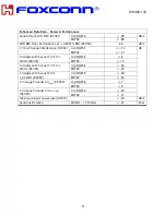
C/I Image CH interference (RCV03) 

C/I

image


≤ -9 

C/I

image±1MHz


≤ -20 

Out of band Blocking (RCV04) 

30MHz – 2000 MHz 

-10 

dBm 

2003MHz – 2399MHz 

-27 

2484MHz –  2997MHz 

-27 

3000MHz –  12750MHz 

-10 

Intermodulation Performance at ≤ 0.1% BER (RCV05) 

-64 

dBm 

Maximum input power level 


≥ -20 

dBm 

Spurious Emission 

30MHz – 12.75GHz 

≤ -57 

dBm 

Summary of Contents for WBU063-VZ

Page 1: ...1a b g n ac WLAN 2T2R BT v5 1 Combo Module Product Specification 3 0 Approved Approved Prepared by ________________________ _________________________ _________________________ Zeke Wu Ben Ho Kevin Man...

Page 2: ...athy Kuo Updated page 18 22 Regulatory statement RESTRICTED AND CONFIDENTIAL INFORMATION STATEMENT All information contained in this document is the exclusive property of Foxconn Technology Inc and it...

Page 3: ...oth subsystem contains the Bluetooth radio baseband link controller It also uses the 32 bit RISC MCU for the Bluetooth protocols 1 1 Key Characteristic 32 bits RISC MCU for Wi Fi protocols IEEE 802 11...

Page 4: ...ew Table 1 Pin Definitions Pin number Symbol name Type Pin description 1 VBUS Power DC 5V 2 VBUS Power DC 5V 3 WoBLE I O BT_wake on 4 GND GND Ground 5 GND GND Ground 6 DM I O USB data 7 DP I O USB dat...

Page 5: ...n Description Typical Unit IDLE mA 2G 2T N mode HT 40MHz MCS 7 mA 2G 2T N mode HT 20MHz MCS 7 mA 2G 2T G mode OFDM54M mA 2G 2T B mode CCK11M mA 5G 2T N mode HT 40MHz MCS 7 mA 5G 2T N mode HT 20MHz MCS...

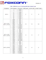
Page 6: ...1 dBm 802 11b 1 DBPSK 13 5 13 5 16 5 2 DQPSK 5 5 CCK 11 CCK 802 11g 6 OFDM 15 15 18 9 OFDM 12 OFDM 18 OFDM 24 OFDM 36 OFDM 48 OFDM 54 OFDM 802 11n HT20 MCS0 BPSK 14 5 14 5 17 5 MCS1 BPSK MCS2 QPSK MCS...

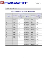
Page 7: ...02 11n HT20 802 11ac VHT20 MCS0 BPSK 11 5 11 5 14 5 MCS1 BPSK MCS2 QPSK MCS3 QPSK MCS4 16 QAM MCS5 16 QAM MCS6 64 QAM MCS7 64 QAM 802 11n HT40 802 11ac VHT40 MCS0 BPSK 14 14 17 MCS1 QPSK MCS2 QPSK MCS...

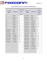
Page 8: ...5 HT20 MCS1 QPSK 91 5 5 5 CCK 93 5 HT20 MCS2 QPSK 88 5 11 CCK 90 5 HT20 MCS3 16 QAM 86 6 OFDM 95 5 HT20 MCS4 16 QAM 82 5 9 OFDM 93 HT20 MCS5 64 QAM 78 5 12 OFDM 92 5 HT20 MCS6 64 QAM 76 5 18 OFDM 90 H...

Page 9: ...36 OFDM 82 HT40 MCS5 64 QAM 73 5 48 OFDM 77 5 HT40 MCS6 64 QAM 72 5 54 OFDM 76 HT40 MCS7 64 QAM 71 HT20 MCS0 BPSK 93 5 HT40 MCS8 256 QAM 66 HT20 MCS1 QPSK 90 HT40 MCS9 256 QAM 65 HT20 MCS2 QPSK 87 5...

Page 10: ...5 825GHz 47 Modulation Characteristic TRM07 Delta f1 avg 140 f1avg 175 kHz Delta f2 max 115 at 99 9 Delta f2 avg Delta f1 avg 0 8 Initial Carrier Frequency Tolerance TRM08 75 kHz Carrier Frequency Dri...

Page 11: ...QPSK 8DPSK 10 Basic Data Rate Receiver Performance Sensitivity at 0 1 BER RCV01 02 81 dBm C I Co Channel interference RCV03 11 dB C I Adjacent CH interference RCV03 f f0 1MHz 0 f f0 2MHz 30 f f0 3MHz...

Page 12: ...4 DQPSK 13 dB 8DPSK 21 C I Adjacent Channel C I f f0 1MHz RCV09 4 DQPSK 0 8DPSK 5 C I Adjacent Channel C I f f0 2MHz RCV09 4 DQPSK 30 8DPSK 25 C I Adjacent Channel C I f f0 3MHz RCV09 4 DQPSK 40 8DPSK...

Page 13: ...Drift TRM LE06 07 Center frequency 150 kHz During any packet 50 Maximum Drift Rate TRM LE06 07 20 Hz 50 us Receiver Performance Sensitivity at 30 8 PER 0 1 BER RCV LE01 02 81 dBm C I Co Channel inter...

Page 14: ...WBU063 VZ 13 2 7 Environment Specifications Operating Conditions preliminary Operation Temperature 0 60 Storage Conditions preliminary Non Operation Temperature 10 60 Typ 25...

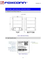
Page 15: ...WBU063 VZ 14 CHAPTER3 MECHANICAL SPECIFICATION 3 1 Module Assembly Dimension Figure 2 Mechanical Drawing 3 2 Label Specification Figure 3 Label Drawing...

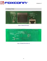
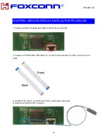
Page 16: ...WBU063 VZ 15 3 3 Module Photo Figure 4 Module Photo top Figure 5 Module Photo bottom...

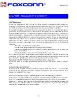
Page 17: ...N PROCEDURE 1 Prepare wireless module and open connector as red part 2 Prepare a FFC Flexible Flat Cable to connect with wireless module connector and press 3 Another FFC site to connect with host mai...

Page 18: ...equipment and receiver Connect the equipment into an outlet on a circuit different from that to which the receiver is connected Consult the dealer or an experienced radio TV technician for help FCC Ca...

Page 19: ...portable condition will need a separate reassessment through a class II permissive change application or new certification End Product Labeling This transmitter module is authorized only for use in d...

Page 20: ...nual The host integrator must follow the integration instructions provided in this document and ensure that the composite system end product complies with the requirements by a technical assessment or...

Page 21: ...ul interference to co channel mobile satellite systems D claration d exposition aux radiations Cet appareil est conforme aux limites d exposition aux rayonnements d finies pour un environnement non co...

Page 22: ...nd operated with greater than 20cm between the antenna and users The final end product must be labeled in a visible area with the following Contains IC 2878F WBU063VZ Plaque signal tique du produit fi...

Page 23: ...ibited for use with this device WLAN Type PIFA Internal BT Type PIFA External ANTENNE Les antennes suivantes ont t certifi es pour une utilisation avec ce module des antennes du m me type gain gal ou...

Reviews: