background image

THEA-130 / 160 Sprayer Drone 

 User Manual

©

2019 FOXTECH All Rights Reserved


9

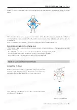
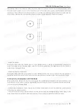
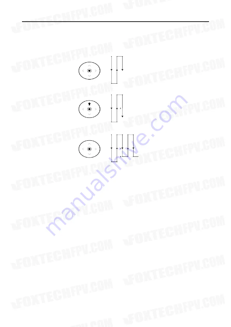
Shorten the route of the AB point: When the drone flies to a position close to the shortened position, push 
the pitch switch (push or pull, to the far end is pull, to the near end is push), and the drone will slowly 
advance at 2m/s. When the shortened position is reached, the pitching switch is back to center and the 
drone stops, and then the corresponding route is copied, and the AB point  route is shortened.

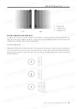
- Adjust the altitude 
During the flight, when the throttle stick is in the middle position, it will fly in a fixed-height status(with a 
radar,can realize terrain following flight), when the throttle is pushed up, the height rises and the throttle is 
pulled down, the height drops.

- Adjust the direction of the nose
During the flight, when the yaw joystick is in the middle position, the nose is locked, the yaw joystick is 
pushed to the left, the drone turns to left, when the yaw joystick is pushed to right, the drone turns to right.

Continue to fly at breakpoints in AB Point Mode

When exiting from AB point mode, the drone saves the current spray breakpoint, AB point definition, and 
task direction. If you want to use the original AB point record and continue to perform the AB point mode, 
you can follow the following steps:

- In the manual stabilization mode, the remote controller E dial switch is set to the AB mode, and the drone 
is hovering at a certain position.
- The pitch channel is fully pushed forward, and the drone enters the breakpoint-flying mode, flying to the 
place where the drone exited the AB mode last time. Then continue to perform in AB point mode.

Summary of Contents for THEA-130

Page 1: ...User Manual V1 0 THEA 130 160 Sprayer Drone 2019 04...

Page 2: ...point Mode Repair and Maintenance Replace the Propeller Replace the Motor Replace the ESC Replace Nozzles Replace the Pump Cleaning After Use System Introduction System Characteristic Introduction to...

Page 3: ...ontrol Voltage Detection and Protection Area Limited Protection Ground Station Setting Equipment Connection Function Introduction Route Planning Ready to Take Off RTK Use Instructions Concise Operatio...

Page 4: ...ave read understood approved and accepted all terms and conditions of the product s instructions disclaimers and safety instructions The user is committed to being responsible for his or her actions a...

Page 5: ...ad understood approved and accepted all terms and conditions of the product s instructions disclaimers and safety instructions The user is committed to being responsible for his or her actions and all...

Page 6: ...ease recalibrate the compass when replacing a remote area Flight Operation Environmental Requirements Pre flight Check Compass Clibration Make sure that the drone battery remote control battery and gr...

Page 7: ...lowing case The compass data is abnormal the LED status indicator of the drone indicates that the yellow green light flashes alternately The flight field is far from the site where the last calibratio...

Page 8: ...stabilization mode if you do not want to use the AB point information of the previous trip you can continuously dial the G dial 7 8 times to clear the AB record to ensure that there is no AB point ins...

Page 9: ...g of the route in AB point mode realized by the following method please pay attention Regulated ridge length Extension of AB point When the plane flies to the edge push the pitch switch push or pull t...

Page 10: ...ottle is pulled down the height drops Adjust the direction of the nose During the flight when the yaw joystick is in the middle position the nose is locked the yaw joystick is pushed to the left the d...

Page 11: ...at AB point mode When the drone is performing AB point task after encountering obstacles in front first dail the roll joystick the drone will stop then will move to the direction to which the roll joy...

Page 12: ...ith four M3X10 screws Insert the nozzle into the nozzle fixed rod Note the connection part of nozzle and hose need to be inserted into the fixing rod gap Place the nozzle clamp into the nozzle and fix...

Page 13: ...each use Step1 Remove the filter from the nozzle and wash off the attachment Step2 Wash the aircraft pesticide tank with soapy water Step3 Clean the aircraft pesticide tank with clean water Step4 Inst...

Page 14: ...nd flexible task control function and users can use ground station software to make a variety of flight tasks conveniently service The Paladin system integrates high precision inertial and satellite n...

Page 15: ...of the throttle can be fixed but the precise fixed point suspension cannot be realized and manual correction is required When the satellite signal is good Hovering can be done with high precision and...

Page 16: ...nd station users Ultrasonic sensor which is used for imitate terrain flight and fixing height at low attitude Data transmission checkpoint based on Bluetooth which is applicable for ground station on...

Page 17: ...f Version 2 flight controller power module DC 24V 6S 50V 12S Power supply range of RTK base station DC 24V 6S 50V 12S Power supply range of RTK board DC 12V 3S 50V 12S Power supply range of water pump...

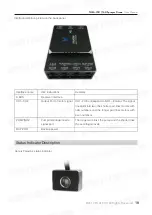
Page 18: ...uge Reserved Radar Data transmission radio External indicator Power interface Remarks It should be pasted at the bottom of medicine box with free nail glue There should be nothing blocked in the range...

Page 19: ...erface Output Port of motor signal Pump Centrifugal nozzle signal port Backup power Remarks CH1 CH8 correspond to NO 1 8 motor The signal line splits into two the shorter part links motors with odd nu...

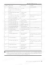
Page 20: ...n light flashes quickly Malfunction status It s crashed The flight controller is initializing The equipment is not calibrated The equipment is being calibrated or tested Remote control failure Low pow...

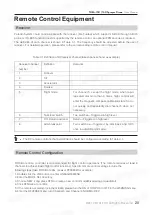
Page 21: ...eated dial more than 6 times flight control will enter the magnetic compass calibration state So do not quickly and repeatedly dial channel 5 when not necessary Two switches Triggered in high level Re...

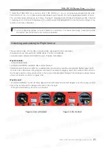
Page 22: ...rcraft can take off only after unlocking take Japanese Hand as example Unlockable mode Altitude Hold GNSS Assist Position Hold Mode Lockable mode Altitude Hold GNSS Assist Position Hold Mode Waysto Un...

Page 23: ...push the accelerator motor rotates calibration completed c Repeat the above steps for other ESC calibration Flight control ESC calibration steps ESC signal lines and receivers have access to flight co...

Page 24: ...Return 1 Not Open 2 Hovering 1 The maximum angle of flight 35 2 Out of control protection angle of 60 Description Protective measures valid or invalid Protection mode optional Protective measures vali...

Page 25: ...return process the aircraft will hover for 2 seconds to perform autonomous landing The returning logic execution diagram is Remote control is the most direct means of control the aircraft from a secur...

Page 26: ...fe protection is set to be valid only in the fully autonomous mode and the remote controller signal loss The manual mode fixed height positioning and the AB point mode cannot be triggered Autonomous m...

Page 27: ...t connected will pop up the following dialog box select Connect to connect the drone Connect handheld mapping device to connect the handheld mapping device Connect RTK mapping device to connect RTK ma...

Page 28: ...THEA 130 160 Sprayer Drone User Manual 2019 FOXTECH All Rights Reserved 27 3 Waiting for the drone to be connected voice prompt Function Introduction 1 Main interface function...

Page 29: ...9 FOXTECH All Rights Reserved 28 2 Click Display Seetings the user can select the parameter item you need up to 6 items Click Setting then will pop up the dialog box Task Statistics the cumulative num...

Page 30: ...tor motors are normal please test away from the crowd to prevent accidents Remote Control Calibration Check if the remote control joystick is in the position shown below check the status of each chann...

Page 31: ...THEA 130 160 Sprayer Drone User Manual 2019 FOXTECH All Rights Reserved 30 Calibration Setting Calibrate accelerometer horizontal calibration dynamic balance correction 3 Control Sensitivity Setting...

Page 32: ...THEA 130 160 Sprayer Drone User Manual 2019 FOXTECH All Rights Reserved 31 4 Safety Setting 5 Agriculture Plant Protection Setting...

Page 33: ...THEA 130 160 Sprayer Drone User Manual 2019 FOXTECH All Rights Reserved 32 6 System Setting including system version etc Route Planning 1 Click enter the route planning interface...

Page 34: ...rkers as the edge of the work area in the map at least three points form an area 3 Mark the obstacle area in the work zone Click enter the marker mode then select 2 Obstacle obstacle area select to cr...

Page 35: ...4 Click the on the left to generate the route the top parameters can be edited separately From left to right the route interval flight speed start position of the route route angle obstacle avoidance...

Page 36: ...Rights Reserved 35 5 After the route planning is completed click on the left side upload the route to the aircraft 6 After the upload is completed you need to click to download the route and ensure t...

Page 37: ...k the aircraft takes off automatically the height is 2m 3 Click the aircraft enters the autonomous operation mode and will fly following the route that has already been uploaded 4 After the flight is...

Page 38: ...THEA 130 160 Sprayer Drone User Manual 2019 FOXTECH All Rights Reserved 37 RTK Use Instructions...

Page 39: ...THEA 130 160 Sprayer Drone User Manual 2019 FOXTECH All Rights Reserved 38...

Page 40: ...connect RTK base station When prompted connection XXX success it means that Bluetooth connection is successful When prompted connection XXX failed it means that Bluetooth connection is failed When pr...

Page 41: ...en calibrated skip 10 set flight model 11 set protection of being out of control 12 check if there is any warning from the ground station analyze the reasons and solve it 13 check if key data is norma...

Page 42: ...damage to the aircraft structure and fly dangers 10 Be far away from propellers rotating at high speed 11 Check every device before flying if the key devices don t work normally and don t force it to...

Page 43: ...m the magnetic compass is right for example if the aircraft turns around the course will change 360 degrees and observe if the course data from the ground station is with the actual match 3 Rotating s...

Page 44: ...ranty Not follow instructions provided by BOYING when installing or operating Performance problems caused by man made improper operation or chemical agents Performance problems caused by the unofficia...

Page 45: ...ish Finally if you need to connect the flight control to the ground station using USB cable please make sure that you have chosen the right driver as shown below Install data transmission driver The f...

Page 46: ...content is subject to change Download the latest version from https www foxtechfpv com thea 130 agriculture spraying drone html https www foxtechfpv com thea 160 agriculture sprayer html For everyday...

Reviews: