Integrated interfaces
27
6.7.1 Analogue inputs 0 to 10 V/0 to 20 mA
(P0 to P3)
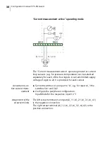
The four analogue inputs can be individually switched electron-
ically between 0 to 10 V and 0 to 20 mA. In operating mode
0 to 20 mA, 2 switches can be used to switch between passive
and active current measurement for each channel. The factory
setting is 0 to 10 V.
The following table shows the configuration possibilities of the
inputs.
Key figures at a glance
– 4x analogue inputs
– Voltage input: 0 to 10 V, Ri=100 k
Ω
– Current input (passive): 0 to 20 mA, Ri=100
Ω
– Current input (active): 0 to 20 mA
– Module address:
C092
– Name of connection terminals:
AI_1.1
to
AI_4.2
Input
Operating mode Switch position Peripheral configuration
AI_1
0 to 10 V
SA1 = P, SA2 = P None
AI_1
0 to 20 mA passive SA1 = P, SA2 = P
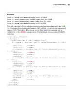
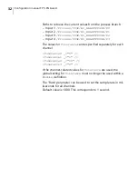
<InputMode0 _="I"/>
AI_1
0 to 20 mA active SA1 = P, SA2 = A
<InputMode0 _="I"/>
AI_2
0 to 10 V
SA3 = P, SA4 = P None
AI_2
0 to 20 mA passive SA3 = P, SA4 = P
<InputMode1 _="I"/>
AI_2
0 to 20 mA active SA3 = P, SA4 = A
<InputMode1 _="I"/>
AI_3
0 to 10 V
SA5 = P, SA6 = P None
AI_3
0 to 20 mA passive SA5 = P, SA6 = P
<InputMode2 _="I"/>
AI_3
0 to 20 mA active SA5 = P, SA6 = A
<InputMode2 _="I"/>
AI_4
0 to 10 V
SA7 = P, SA8 = P None
AI_4
0 to 20 mA passive SA7 = P, SA8 = P
<InputMode3 _="I"/>
AI_4
0 to 20 mA active SA7 = P, SA8 = A
<InputMode3 _="I"/>
Summary of Contents for 50.0070.0001.00
Page 1: ...Configuration manual FP S ENGuard ...
Page 92: ...Configuration manual FP S ENGuard 92 ...
Page 96: ...Notes 96 ...
Page 97: ...Notes 97 ...
Page 98: ...51 0070 9031 00 Rev 00 2020 08 xxx helbig berlin ...


