Configuration manual FP S-ENGuard
66
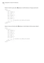
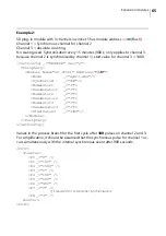
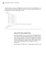
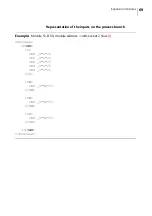
Values for the second cycle after
50
pulses on channel 2 and 3. For simplification, it is
assumed that the synchronous pulse for channel 1 occurs simultaneously with the in-
ternal synchronous event after 900 seconds.
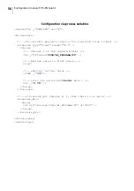
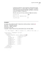
<C63C>
Counter>
<P0 _="0" />
<P1 _="50" />
<P2 _="1550" />
<P3 _="0" />
<P4 _="50" />
<P5 _="150" />
<P6 _="900" />
<P7 _="0" />
(1 if read within 1 second after synchronisation)
<P8 _="3" />
<Counter>
<C63C>
Using the S0 inputs as digital inputs
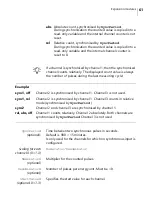
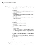
The three S0 inputs can also be used as normal digital inputs. In
this case the inputs are switched passively, e.g. passive contact
such as relays or buttons. This does not require any configura-
tion to be transferred to the device. The digital input values of
the three S0 inputs are mapped in the process branch via the
input variables P9 (channel 1), P10 (channel 2) and P11
(channel 3).
An open input has logic level 1, a closed input has logic level 0.
Summary of Contents for 50.0070.0001.00
Page 1: ...Configuration manual FP S ENGuard ...
Page 92: ...Configuration manual FP S ENGuard 92 ...
Page 96: ...Notes 96 ...
Page 97: ...Notes 97 ...
Page 98: ...51 0070 9031 00 Rev 00 2020 08 xxx helbig berlin ...

