11
ENGLISH
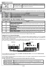
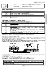
Connection to a control panel with double balancing inputs (only Fracarro control panels):
If you are connecting MOD-WL04 to a wired control panel that operates even with double balancing inputs insert jumper
MODE of the module. Using this type of connection, on the terminals related to the 4 available zones will be communicated
both alarm and tamper devices information. In case of installation of a siren or wireless dialler, the output Out2 must be con-
nected to the control panel in order to provide the tamper information of these devices.
ATTENTION: If MOD-WL04 must be installed within a control panel close the connector TMPR (Fig. 1: 5) with a
jumper.
INSTALLING
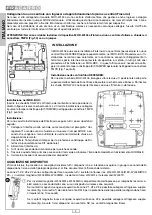
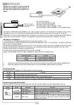
The MOD-WL04 may be installed within a Control panel (for example within the new
Fracarro Defender wired control panels) or separately in the MOD-BOX.
In the first case proceed with the installation only if the panel has adequate interior
space to allow the housing and has no metal cover; in all other cases install the
module in the MOD-BOX. In this case it is necessary to connect the tamper button
TMPR into the connector (Fig. 1: 5).
Installing in the control panel DEFENDER:
To insert the card MOD-WL04, unscrew the two screws at the
top of the board of the Control panel and tilt the board down.
Then fix MOD-WL04 card at the bottom with two screws provided.
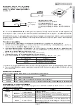
Installing the MOD-BOX:
Insert the card MOD-WL04 within the box in the position indicated
in the figure. Fix the card using the 4 screws provided and connect
tamper button (KIT-TAMPER) in the connector TMPR
(Fig. 1 point 5).
Installation:
For a proper installation of the interface follow the steps below:
1. 1. Connect the interface to the control panel as shown in the paragraph
“Connections”; close or remove the jumper mode, depending on whether
there are used outputs normally closed or double balancing;
2. 2. Connect the tamper switch for the protection of the interface from
removal (optional kit);
3. 3. Power up the interface;
4. 4. All the LED light up in orange for a few seconds;
5. 5. After this time only the green led is on and indicates the beginning of
the normal mode operation;
6. 6. Start the acquisition of devices.
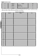
DEVICES ACQUISITION
Before starting the procedure is recommended to divide all the devices to be acquired into groups according to the location
or type, in order to increase the efficiency of the system.
The zones Z1, Z2, Z3, Z4 are set for the acquisition of all the infrared detectors (WL04IR, WL04IR EX, WL04BIR100EX...),
magnetic detectors (WL04MB and WL04MM), smoke detectors WL04RF and remote controls WL04TC.
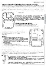
For magnetic detectors WL04MB and WL04MM, the behaviour of the input of wired devices changes
depending on which zone the detectors are acquired.
If the magnetic contacts are acquired on zones Z1, Z2, Z£ it’s possible to connect to the additional input
(fig.A, terminal 1) detector for shutter protection, RF45 (set configuration: 4 pulses in 10 seconds)
If the magnetic contacts are acquired on zone Z4 it’s possible to connect devices with normally closed
contact to the additional input, for example wired magnetic device. (fig. A 1)
MOD-WL04
MOD-WL04
A


