Transport platform
SEP Serie
SEP u
ser’s manual Page 14 of 89
Doc no. RD-7243-MA-001-02
4. Technical data
4.1. General data
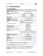
FRACO GENERAL DATA - SEP
Technical
Nominal speed (vertical travel)
0-40 ft/min (0-12,2 m/min)
Speed governor activation speed (centrifugal
brake)
85 ft/min (26 m/min)
MAXIMUM
number of persons on the platform
13 persons (Equally distributed)
Mast section type
Single rack
(13090104)
26" x 26" x 5'-0"
(650 mm x 650 mm x 1,5 m)
Double rack
(13090137)
26" x 26" x 5'-0"
(650 mm x 650 mm x 1,5 m)
Mast section weight
300 lb (136 kg)
305 lb (138 kg)
Mast section height
5'-0" (1,5 m)
*
MAXIMUM
freestanding installation height
(without anchor)
* With adjustable legs:
Prohibited!
MAXIMUM
installation height (anchored)
1 300 ft (400 m)
**
MAXIMUM
first anchor installation height
**
With adjustable leg 20 ft (6,0 m)
MAXIMUM
height over the last anchor (highest
anchor)
During operation
: 0 ft (0 m) MAX from the platform floor to the
last anchor.
During installation
: 0 ft (0 m) MAX from the top of the
protection roof to the last anchor (highest anchor).
*** "Typical" spacing between anchors
***
30 ft (9,0 m)
MIN 20 ft (6,0 m)
MAX 40 ft (12,0 m)
Spacing between cable guides
MAX 20 ft (6,0 m)
Pay load
MAXIMUM
(Capacity)
Important!
Deduce the average load of workers
and their personal equipment.
∞
S
EE SECTION
ON PAGE
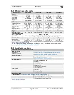
Depending on model
5 000 lb (2 270 kg)
6 000 lb (2 720 kg)
7 000 lb (3 175 kg)
8 000 lb (3 630 kg)
MAXIMUM load during installation, assembly and
disassembly.
Depending on model
Operation temperature
Do not operate below -4°F (-20°C).
Note:
it is recommended to use the permanent heating system if
the platform is used in a [41°F (5°C) à -4°F (-20°C)] environment
REFER TO SECTION
ON
PAGE
MAXIMUM dynamic speed of the wind
During installation (assembly/disassembly)
28 mi/h (45 km/h)
Freestanding
28 mi/h (45 km/h)
In service
35 mi/h (55 km/h)
Out of service
Refer to local regulation in effect
Electrical characteristics
Power outage
Specific to each unit
(See identification pate and engineering package specific to the
project for electrical data)
∞
S
EE SECTION
ON PAGE
Energy consumption
VFC
Disk traction force
Table 2
– General data
* Base with
adjustable jack legs
: freestanding use/installation is
forbidden at all time.
The mast must be supported with
a crane or an independent lifting system for the installation of the first two (2) anchors.
** Base with
adjustable jack legs
: the first anchor must be put in place within the 20'-0" (6m) from the ground. Install the
subsequent anchors at
"typical"
spacing from one another. See
« *** »
bellow.
***
The typical spacing between anchors is 30'-0" (9 m) ± 10'-0" (3 m), however
it is forbidden
to install two (2)
subsequent anchors with more than a 10'-0" (3 m) difference compared to the two next/previous anchors set.
Valid example
: (anchors 1-2 = distance of 25'-0" (7,5 m) and anchors 2-3 = distance of 35'-0" (10,5 m)).
Invalid example
:(anchors 1-2 = distance of 25'-0" (7,5 m) and anchors 2-3 = distance of 40'-0" (12 m)).
Summary of Contents for SEP-5000
Page 1: ......


