background image

USER MANUAL 

Micro Reach Xtend

TM

 (NN01-110) 


Last updated on May 2020


© 2020 FRACTUS ANTENNAS, S.L.   -  


12


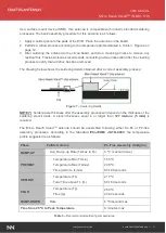
Next graphic shows temperature profile (grey zone) for the antenna assembly process in reflow 
ovens. 
 

Figure 8


 Temperature profile. 


6.


PACKAGING 


The Micro Reach Xtend

™ chip antenna is available in tape and reel packaging. 


Measure 

mm 

12.0 ± 0.3 

A0 

2.5 ± 0.1 

B0 

4.9 ± 0.1 

K0 

1.3 ± 0.1 

B1 

5.3 ± 0.1 

1.55 ± 0.05 

D1 

1.55 ± 0.05 

Wmax 

12.3 

1.5 ± 0.1 

5.5 ± 0.1 

1.5 ± 0.1 

4.5 ± 0.1 

P0 

4.5 ± 0.1 

P2 

1.5 ± 0.1 


Figure 9 

– 

Tape Dimensions and Tolerances.


Summary of Contents for Micro Reach Xtend NN01-110

Page 1: ...lop innovative products and accelerate their time to market through our expertise in antenna design testing and manufacturing Micro Reach XtendTM NN01 110 Fractus Antennas products are protected by Fractus patents All information contained within this document is property of Fractus Antennas and is subject to change without prior notice Information is provided as is and without warranties It is pr...

Page 2: ...t updated on May 2020 2020 FRACTUS ANTENNAS S L 2 INDEX OF CHAPTERS 1 ANTENNA DESCRIPTION 4 2 QUICK REFERENCE GUIDE 4 3 ELECTRICAL PERFORMANCE 5 4 MECHANICAL CHARACTERISTICS 9 5 ASSEMBLY PROCESS 10 6 PACKAGING 12 7 PRODUCT CHANGE NOTIFICATION 14 ...

Page 3: ...PERFORMANCE 5 3 1 EVALUATION BOARD 5 3 2 MATCHING NETWORK 5 3 3 VSWR AND EFFICIENCY 6 3 4 RADIATION PATTERNS 2 4 2 5 GHz GAIN AND EFFICIENCY 7 3 5 CAPABILITIES AND MEASUREMENT SYSTEMS 8 4 MECHANICAL CHARACTERISTICS 9 4 1 DIMENSIONS AND TOLERANCES 9 4 2 SPECIFICATIONS FOR THE INK 9 4 3 ANTENNA FOOTPRINT 10 5 ASSEMBLY PROCESS 10 6 PACKAGING 12 7 PRODUCT CHANGE NOTIFICATION 14 ...

Page 4: ...ss epoxy substrate APPLICATIONS Headsets Hearing aids USB Dongles Medical devices Handsets Sensors Proximity etc BENEFITS Small form factor and footprint Reduced clearance area within PCB Cost effective Easy to integrate pick and place 2 QUICK REFERENCE GUIDE Technical Features 2 4 2 5 GHz Average Efficiency 55 Peak Gain 0 2 dBi VSWR 2 5 1 Radiation Pattern Omnidirectional Polarization Linear Weig...

Page 5: ...s covers connectors etc affect the antenna performance This is the reason why it is highly recommended placing pads compatible with 0402 and 0603 SMD components for a PI matching network as close as possible to the antenna feeding point Do it in the ground plane area not in the clearance area This is a degree of freedom to tune the antenna once the design is finished and taking into account all el...

Page 6: ... Board Value Part Number 6 8 nH LQW15AN6N8G80 1 5 pF GJM1555C1H1R5WB01 Figure 2 Matching network implemented in the evaluation board Figure 1 3 3 VSWR AND EFFICIENCY VSWR Voltage Standing Wave Ratio and Total Efficiency versus Frequency GHz Figure 3 VSWR and Total Efficiency vs Frequency GHz from the evaluation board Figure 1 1 See terms and conditions for a free NN Wireless Fast Track service in ...

Page 7: ... Elevation Cut 90 Plane YZ at 2 45 GHz Gain Peak Gain 0 1 dBi Average Gain across the band 0 2 dBi Gain Range across the band min max 0 6 0 1 dBi Efficiency Peak Efficiency 56 7 Average Efficiency across the band 55 2 Efficiency Range across the band min max 53 0 56 7 Table 2 Antenna Gain and Total Efficiency from the evaluation board Figure 1 within the 2 4 2 5 GHz band Measures made in the evalu...

Page 8: ...return on investment throughout the product development process We also provide our clients with the opportunity to leverage our in house testing and measurement facilities to obtain accurate results quickly and efficiently Agilent E5071B VSWR S Parameters Radiation Pattern Efficiency SATIMO STARGATE 32 Anechoic chambers and full equipped in house lab 2 2 5 3 3 5 4 4 5 5 5 5 6 20 18 16 14 12 10 8 ...

Page 9: ...the antenna indicates the feed pad Measure mm A 4 1 0 2 B 2 0 0 2 C 1 0 0 2 D 0 5 0 1 Figure 4 Antenna Dimensions and Tolerances The Micro Reach XtendTM chip antenna is compliant with the restriction of the use of hazardous substances RoHS The RoHS certificate can be downloaded from www fractusantennas com 4 2 SPECIFICATIONS FOR THE INK Next figure shows the correct colors of the antenna Acceptabl...

Page 10: ...8 D 0 5 E 1 7 F 0 5 G 3 7 H 5 0 I 7 5 Tolerance 0 2mm Figure 5 Antenna Footprint Details Other PCB form factors and configurations may require a different feeding configuration feeding line dimensions and clearance areas If you require support for the integration of the antenna in your design please contact support fractusantennas com 5 ASSEMBLY PROCESS Figure 6 shows the back and front view of th...

Page 11: ...g details obtained after a correct assembly process Figure 7 Soldering Details NOTE Solder paste thickness after the assembly process will depend on the thickness of the soldering stencil mask A stencil thickness equal to or larger than 127 microns 5 mils is required The Micro Reach XtendTM antenna should be assembled following either Sn Pb or Pb free assembly processes According to the Standard I...

Page 12: ...enna assembly process in reflow ovens Figure 8 Temperature profile 6 PACKAGING The Micro Reach Xtend chip antenna is available in tape and reel packaging Measure mm W 12 0 0 3 A0 2 5 0 1 B0 4 9 0 1 K0 1 3 0 1 B1 5 3 0 1 D 1 55 0 05 D1 1 55 0 05 Wmax 12 3 E 1 5 0 1 F 5 5 0 1 K 1 5 0 1 P 4 5 0 1 P0 4 5 0 1 P2 1 5 0 1 Figure 9 Tape Dimensions and Tolerances ...

Page 13: ...ch XtendTM NN01 110 Last updated on May 2020 2020 FRACTUS ANTENNAS S L 13 Figure 10 Images of the tape Measure mm A max 180 0 1 0 G 13 5 0 2 t max 17 5 0 2 Reel Capacity 2500 antennas Figure 11 Reel Dimensions and Capacity ...

Page 14: ... X Processing Manufacturing X Other Logo product color and Part Number Change description 1 Part Number From FR05 S1 N 0 110 FRACTUS to NN01 110 FRACTUS ANTENNAS in the User Manual 2 Pads END From circular to rectangular 3 Color From blue white to white black OLD NEW Comments 1 Footprint in the PCB to solder the chip antenna remains the same 2 The matching network to properly tune the chip antenna...

Reviews: