50 ______________________________________________________________ NT 1963 E – 07/2020
5.2.4.
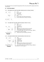
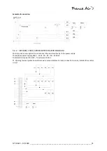
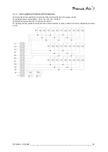
SIZE 8000 TO 16,000 MOTOR WIRING DIAGRAM (400 VAC THREE-PHASE)
5.3.
ELECTRIC HEATERS
5.3.1.
CONNECTION RECOMMENDATIONS
Since the control system is not supplied with the heaters, you need to:
- fit in a control circuit the opening thermal prot manual and opening reset + automatic reset, connected
in series.
- monitor for flow shortages (e.g. with a pressure switch). The resistors must never be powered in the absence
of ventilation.
- a post-ventilation time (e.g. with a time lag relay), to dissipate the residual heat from the resistors before the
ventilation is switched off.
- connect the resistors to a contactor, and never directly to the mains power supply.
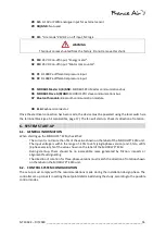
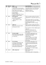
PE
Earth
L1
Supply, phase 1
L2
Supply, phase 2
L3
Supply, phase 3
24V + 24V DC output
10 V + 10V DC output
0V
GND
D1
Digital input (fan on/off), shunted from the factory
E1
0-10V analogue input (rotation speed control)
K1
(11-14) Alarm contact max. 2A, 250 V (see
Motor

