Installation Guidelines
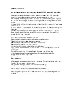
A typical installation and connection routine for the FX560RC searchlight is as follows:
Referring to wiring diagram C29237, a supply is fed to the power supply unit, which then
provides a common feed to the motor gearbox, searchlight, and joystick panel.
The searchlight has been pre-wired with 1 meters of cable from the motor gearbox to junction
box provided. The searchlight head is pre-wired along with the connecting cable to the motor
gearbox.
14 metres of 35mm DC welding cable from the Interface Output Enclosure to the Power Supply
Unit is supplied.
14 metres of 5 core 1.5mm cable from the Interface Output Enclosure to the Power Supply Unit
is supplied.
3 metres of 3 core 1.5mm cable 230v supply to the Interface Input Enclosure is supplied.
2 pair twisted 0.22mm 100ohm screened cable from the Interface Input Enclosure to the
Joystick Control Panel is supplied.
Cables required to be connected by the customer: -
Ethernet cable from the Interface Output Enclosure to the Data Switch.
Fibre Optic cable from the Data Switch to the network.
Ethernet cable from the Interface Input Enclosure to the network.
Ethernet cable from the network to the computer.
3 cores 1.5mm 230v Supply to the Interface Output Enclosure
2 pair twisted 0.22mm 100ohm screened cable from the Interface Output Enclosure to the
Junction Box.
5 cores 2.5mm cable from the Interface Output Enclosure to the Junction Box.
185mm Welding Cables from the Interface Output Enclosure to the Junction Box.
Supply cable to the Power Supply Unit.
Basic Operation
When the searchlight is switched on a supply is fed to the PSU and linked to the ignitor. Also,
from the PSU, a dc output is fed to the lamp.
The ignitor ionises the gas within the lamp, and this strikes the light.
All other facilities are fed via the control panels and motor gearbox.
When the light is in operation, the output from the PSU should be approximately 34.5v dc at
145amps.
Summary of Contents for A7290
Page 6: ......
Page 7: ......
Page 8: ...Remove front panel for AC DC wiring connections Back To Top...
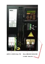
Page 9: ...INPUT 4 CORE 2 5mm TE2 50mm WELDING CABLE S50 2 CORE 1 5mm D1...
Page 10: ......
Page 15: ......
Page 22: ...FBUS Speed Control Board...
Page 50: ......
Page 51: ......
Page 52: ......
Page 53: ......
Page 54: ......
Page 55: ......
Page 56: ......
Page 57: ......

