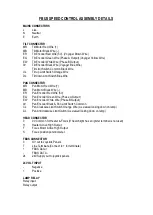
FBUS ADDRESS SWITCHES
OVERVIEW
SETTING LAMP ADDRESS VALUE
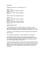
The lamp address is set with the address switches using simple binary input.
Each
switch has a binary value as details below; -
SWITCH 10 = 1
SWITCH 9 = 2
SWITCH 8 = 4
SWITCH 7 = 8
SWITCH 6 = 16
The address value is the sum of the numbers above which are active when
the switch is on. For example, if switches 6 and 8 are on, and all others are
off, the address value would be 5. Note that switches 1-3 are not used for
address selection and should be switched off.
STANDARD CONTROL PANEL
– LAMP ADDRESS
SWITCH NUMBER
VALUE
SWITCH 1
16
SWITCH 2
8
SWITCH 3
4
SWITCH 4
2
SWITCH 5
1
STANDARD CONTROL PANEL
– PANEL ADDRESS
SWITCH NUMBER
VALUE
SWITCH 1
8
SWITCH 2
4
SWITCH 3
2
SWITCH 4
1
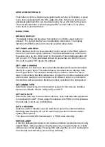
Switching a switch to on, adds the binary value relating to that switch to the
address value. With all switches off the value is zero.
Summary of Contents for A7290
Page 6: ......
Page 7: ......
Page 8: ...Remove front panel for AC DC wiring connections Back To Top...
Page 9: ...INPUT 4 CORE 2 5mm TE2 50mm WELDING CABLE S50 2 CORE 1 5mm D1...
Page 10: ......
Page 15: ......
Page 22: ...FBUS Speed Control Board...
Page 50: ......
Page 51: ......
Page 52: ......
Page 53: ......
Page 54: ......
Page 55: ......
Page 56: ......
Page 57: ......

