E n s u r e t h a t t h e h e a r t h ( s u p e r i m p o s e d o r
constructional) is suitably delineated to discourage
combustible floor finishes from being laid too close to
the appliance, by marking the edges or providing a
change of level.
Position the appliance on the hearth such that
combustible marerial cannot be laid closer to the base
of the appliance than :
(a)
At the front
, 300 mm if the appliance is an open
fire or stove which an, when opened, be operated as
an open fire, or 225 mm in any other case.
(b)
At the back and sides
, 150 mm or in accordance with
the recommendations below which relate to distance
from hearth to walls. Please refer to section J of the
Building regulations.
When using a single wall flue pipe, there must be a
clearance (A) of at least 450 mm from any combustible
materials (timber mantel, girder).
2.3 Chimney
Existing flue
: The chimney must comply with Current
Building Regulations. If in doubt, consult your Dealer or
local Building Inspector.
-
The flue must be in good condition and must provide
sufficient draught (refer to technical details p. 3).
-
The flue must be suitable for the installation of fuel
burning appliances, otherwise it must necessary to
install a tubing.
-
The flue must be
clean
. It should be swept to remove
soot and dislodge tar deposits.
-
The flue must be well insulated. If the flue inner wall
surfaces are cold, a good thermal draw is impossible
causing condensation problems (tar formation etc...)
to occur.
-
The flue must be watertight.
-
The flue must not be shared with other appliances.
-
The chimney must have a constant cross section.
-
When the cross-section of the chimney is too large, it
has difficulties in obtaining a good draught.
-
The chimney must be at least 4.5 m (15 ft) high and be
at 40 cm above the ridge of the roof and 8 meters away
from any construction.
-
In case of a flat roof or when the roof gradient is lower
than 15°, the stack must be 1,2 m (4 feet) high at least.
-
The capping must not restrain the draught.
-
If the chimney has any down draught tendency, due to
its position in relation to nearby obstacles, then an
anti-down draught cowl must be installed on the
chimney or the chimney height must be increased.
-
If the chimney draught is excessive or irregular, a
draught stabilizer (barometric damper) must be
installed to the connector pipe it must be
visible and
accessible
.
Chimney to be built / New flue
: The chimney must
comply with Current Building Regulations. If in doubt,
consult your Dealer or local Building Inspector.
-
The appliance must not support the weight of the flue.
-
It must be distant from any combustible material
(walls, cross members).
-
It must permit an easy sweeping.
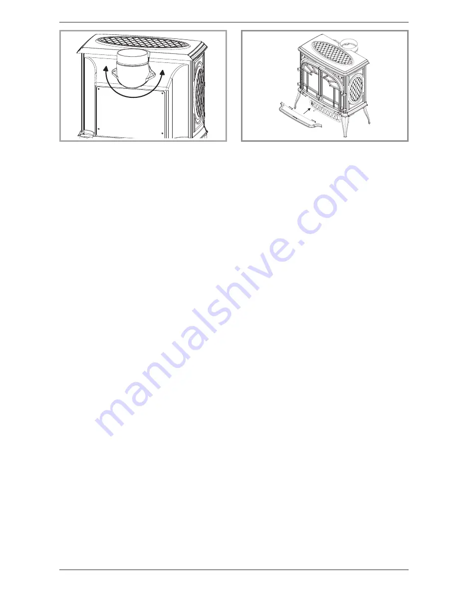
2.4 Mounting the flue collar
The stove is supplied with a connection flue spigot with
an inner diameter of 125 mm and an outer diameter of
139 mm. The same smoke outlet can be used to install a
top or rear flue. All you have to do is remove the
2 screws and turn the adapter 180 degrees (figure 3).
Ensure that the seal is fitted correctly.
2.5 Chimney connector
-
The connection to flue must be carried out according
to local building regulations.
-
The appliance must be installed as close as possible
to the chimney.
-
The connector pipe must be approved for installation
with combustion products (either 24 ga. black painted
or blued steel or 316 grade 20 ga. Stainless steel or
1 mm vitreous enamelled steel).
-
Pipe diameter must not be less than the appliance
spigot diameter. If there is no other solution, the
reduction can not be more than one diameter lower
than the flue spigot and be situated as distant as
possible from the flue connection of the appliance.
-
The connection can be either vertical or horizontal. For
horizontal connections, avoid right angle bends.
-
The join between the connection pipe and the
stovepipe, and the flue, must be leak tight.
-
For the premises equipped with a mechanical
controlled ventilation, the airtightness has to prevent
the exhauster drawing out the smokes from the
exhaust gas pipe.
-
The connection pipe and any draught stabiliser must
have access for cleaning.
Technical manual “1146”
5
“ARDENNES” - model 134 13 15
Installation instructions
Figure 3 - Mounting the flue collar
A
Figure 4 - Mounting the tray
180°


