background image


16


INSTALLATION: 


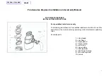
1.      WALL SWITCH 

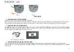
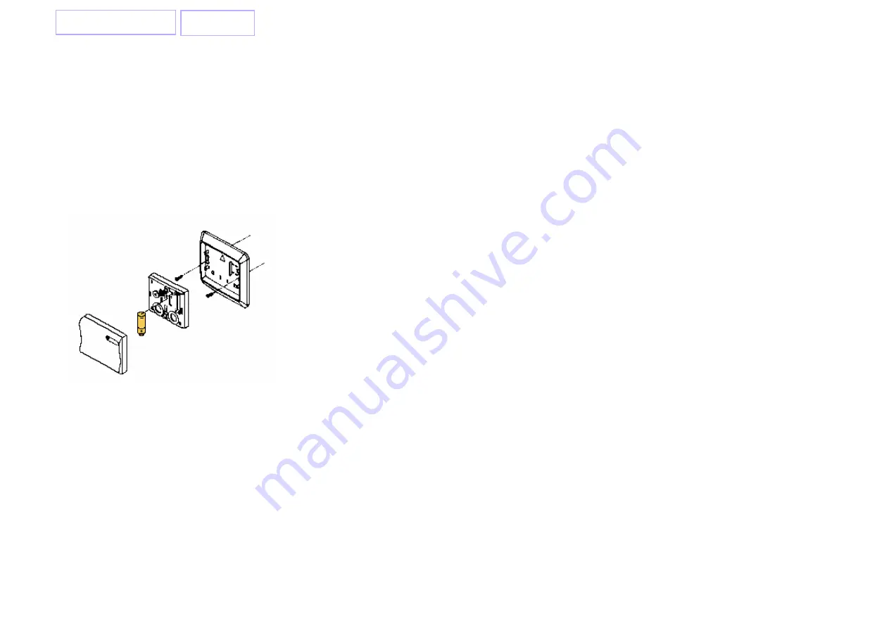
INSERTING THE BATTERY: 

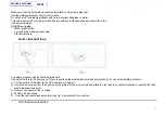
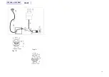
Remove the front casing. Fit the 23A 12V battery (not included)  

into the compartment with battery leads ‘+’ to ‘+’ and ‘-‘ to ‘-‘ 

(fig. 1). 

By pressing the Wall Switch, the LED will illuminate, implying that the battery 
has been inserted properly. 
INSTALLATION: 
To affix the Wall Switch to an existing wall box, simply secure the bottom casing 
to the wall box using the 2 screw provided. Alternatively, you may use the 
double-side tape provided to affix it anywhere you desire. After installing, 
replace the front casing. 


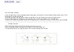
2. 

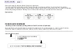
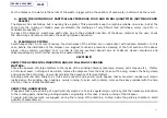
ON/OFF  RECEIVER


Place the receiver into a wall plug (far from water-splash)


Put the disposer’s socket into the receiver (fig. 2) 


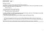
3. WORKING 

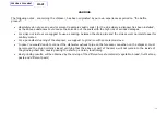
CODES: 

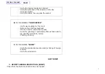
It is possible to change the working code using a screwdriver. Remove the front 
casing of the transmitter to have access to the codes screws. Regulate the 
codes  
The receiver and the transmitter must have the same double-code (Fig. 3) 


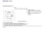
4. USE 
To turn on the disposer push the upper part of the wall switch (transmitter) and 
the LED inside it will flash a green light 
To turn off the disposer push the lower part of the wall switch (transmitter) and 
the LED inside it will flash a red light 


PREVIOUS  DOCUMENT 

START

Summary of Contents for DS LO

Page 1: ... INSTRUCTIONS page 2 OPERATING INSTRUCTIONS page 5 SAFETY INSTRUCTIONS page 6 FOOD WASTE DISPOSER F A Q pag 7 SPARE PARTS EXPLODED VIEW PAG 13 PNEUMATIC KIT FOR DISPOSER pag 16 RADIO CONTROL for DISPOSER pag 17 ADAPTER EXSTENSION FOR DRAIN FOOD WASTE DISPOSER page 19 PREVIOUS DOCUMENT START ...
Page 2: ...wing instructions are for qualified installers to be able to do all the operations in the most correct way according to the electrical and plumbing rules Assembly parts 1 sink stopper 2 sink flange 3 flange gasket 4 flange washer 5 mount ring 6 hinged clump 7 discharge tube 8 tube flange screw 9 tube rubber gasket 10 screws PREVIOUS DOCUMENT START ...
Page 3: ...ump in position paying attention to the installation side To make the join between the garbage disposer and the flange easier you could put some cooking oil on the border of the guard splash ________________________________________________________________________________________________ Plumbing Connection Attach the disposer discharge tube with the tube flange using the given screw Connect the ga...

Page 4: ...e unit and the electrical plant a bipolar switch with minimum nominal flow of 10A according to the required rules The yellow green cable does not have to be interrupted by the switch Before doing the connection please check that the electrical feeding plant has a good ground connection according to the rules required by the law that the plug and the bipolar switch used in the connection are easily...

Page 5: ...ain opening center to the drain pipe OPERATING INSTRUCTIONS 1 Remove the sink drain stopper 2 Turn cold water on to a medium high flow and turn the waste disposer on 3 Put all food waste into the diaposer while the disposer is operating and water running 4 Let the disposer continue to run for about half a minute after the grinding is over 5 Turn the disposer off and leave the water running for hal...

Page 6: ...s SAFETY INSTRUCTIONS The waste disposer has an overload protection If an object falls into the housing or if there is overload the waste disposer stops automatically You should operate as follows 1 Put the switch of the plant in the OFF position or unplug it 2 Insert the hex wrench into the opening at the bottom of the motor shaft and rotate the tool and the counter clockwise to unblock the food ...

Page 7: ... will also give your disposer a fresh clean smell Electrical data TF LO TF MD TF UP 220 240V 50Hz 220 240V 50Hz 220 240V 50Hz 660VA 900VA 1200VA IP 21 IP 21 IP21 FOOD WASTE DISPOSER Checking on line to identify operating faults and card for solution of problems We would like to invite the technician to consider the following cards a simple support or a track in order to obtain information about a ...

Page 8: ...lient Remove the anti flow bulkhead Use more water avoid the dry use Avoid the grinding of particularly fibrous foods and in big quantity artichoke celery Cleaning of piping C TO THE ANWER NOISY Verify the accidental insertion and or falling of foreign matters Verify the lubricarion SECTION A 1 VERIFY THERMAL PROTECTION RESET Check that the thermal protection has not tripped PREVIOUS DOCUMENT STAR...

Page 9: ...he battery of the remote control and eventually replace it 4 VERIFY CABLE PLUG SOCKET Check that the connection phase neutral switch machine has been done correctly Warning Turn off the power before to enter in such part 5 VERIFY PROBABLE GRIPPING Check that foreign matters example spoon or a big quantity of material has not gripped the grinding mechanism Position the switch located on the system ...

Page 10: ...ys drain traps there is an inside anti flow bulkhead to the level of the central coupler Disassemble the draining trap with the help of a proper tool remove this membrane that reducing the useful diameter section might cause obstruction in this point fig 3 Fig 3 BULKHEAD TO BE REMOVED 3 USE MORE WATER AVOID THE DRY USE It is very important to do not load the grinding chamber before the water openi...

Page 11: ...due to sediment cleaner emulsions and calcareous deposit which further reduces the useful diameter SECTION C VERIFY THE ACCIDENTAL INSERTION AND OR FALLING OF FOREIGN MATTERS Check the absence of foreign matters to the inside of the grinding chamber example screws can s tongue etc If after a first visual exam nothing will be visible remove the disposer from the sink take out the plug release the f...

Page 12: ...n pipe and the sink as well normal stopper for sanitary wares For a periodical cleaning of the disposer we suggest to grind ice with some lemon clove In case You would decide to connect the dishwater exhaust pipe on the foreseen connection on the disposer must be removed the plug normally closed verifying that the above or part of the same will not remain to the inside of the grinding chamber caus...

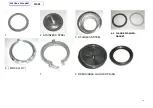
Page 13: ... BLACK SINK FALNGE 3 1940004 FLANGE WASHER 4 1940003 FLANGE GASKET 5 1940005 BLACK MOUNT RING NYLON FIBER GLASS 6 1940025 MOUNT RING ZINC ALLOY 6 1940006 HING CLAMP 7 1940007 GUARD CLAMP 8 1940027 REMOVABLE GUARD SPLASH 8 1940011 RING GASKET TFLO DFLO 14 1940012 RING GASKET TFMD DF MD 14 1940013 EVAPORATOR FIXTURE DF UP TFUP 14 1940008 TUBE RUBBER GASKET AND TUBE SD280 DS MD 16 17 1940026 TUBE RUB...

Page 14: ...14 1 2 STAINLESS STEEL 3 STAINLESS STEEL 4 5 FLANGE WASHER GASKET 6 ZINC ALLOY 7 8 REMOVABLE GUARD SPLASH PREVIOUS DOCUMENT START ...
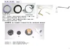
Page 15: ...N FOR FOOD WASTE DISPOSER POSITION 11 1940014 PRESSURE SWITCH POSITION 10 1940015 NUT FIXING PNEUMATIC SET POSITION 9 1940016 RUBBER PUSH BUTTON 16 17 1940026 TUBE RUBBER GASKET TUBE FOR FOOD WASTE DISPOSER SD300 DS UP 16 17 1940008 TUBE RUBBER GASKET TUBE FOR FOOD WASTE DISPOSER DS MD PREVIOUS DOCUMENT START ...
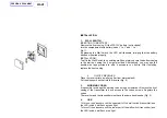
Page 16: ... desire After installing replace the front casing 2 ON OFF RECEIVER Place the receiver into a wall plug far from water splash Put the disposer s socket into the receiver fig 2 3 WORKING CODES It is possible to change the working code using a screwdriver Remove the front casing of the transmitter to have access to the codes screws Regulate the codes The receiver and the transmitter must have the sa...

Page 17: ...O START THE DISPOSER PUSH THE PRESSURE SWITCH AFTER THE USE PUSH AGAIN THE SAME TO STOP THE MACHINE WE RECOMMEND TO OPEN THE WATER TAP FEW SECONDS BEFORE THE START OF THE MACHINE AND KEEP THE ABOVE OPEN FEW SECOND AFTER THE STOP BEFORE THE USE OF YOUR PRESSURE SWITCH PLEASE BE SURE THAT THE PRESSURE SWITCH HAS ACTING ON THE PHASE OF THE ELECTRIC CURRENT CONTRARILY PROVIDE TO INVERT THE POLES OF TH...

Page 18: ...18 Tipo A Tipo B PREVIOUS DOCUMENT START ...
Page 19: ...1940018 RIDUTTORE DA 3 A 2 POLLICI LAVELLO CERAMICA 40 MM ADAPTER DRAIN FROM 3 TO 2 CERAMIC SINK 40 MM PREVIOUS DOCUMENT START ...
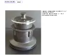
Page 20: ...1940030 PILETTA 3 ALLUNGATA LAVELLO MARMO 350 MM DRAIN 3 EXSTENSION 350 MM PREVIOUS DOCUMENT START ...

Page 21: ...1940031 RIDUZIONE SCARICO 3 A 2 LAVELLO ACCIAIO ADAPTER DRAIN FROM 3 TO 2 STAINLESS STEEL SINK PREVIOUS DOCUMENT START ...

Reviews: