background image

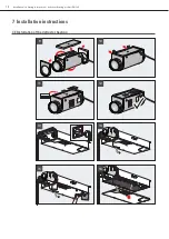
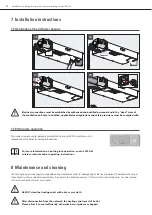
7.3 Installation of the defroster heating

7.4 Putting into operation

7  Installation instructions

The wireless remote control optionally available for the profi-air 180 flat ventilation unit is 
required to put the defroster heating into operation.

The heating spiral must be regularly inspected during maintenance (prior to the beginning of the heating period). The defroster heating or 
the ventilation unit must be disconnected from the network for maintenance work. If there is dirt on the heating spiral, it can be cleaned 
with a suction nozzle and a vacuum cleaner.

For more information on putting into operation, see the 180 flat  
wireless remote control operating instructions.

Do NOT clean the heating spiral with a dry or wet cloth.

After disconnection from the network, the heating spiral may still be hot. 
Please allow it to cool sufficiently, otherwise burn injuries may happen.

Electrical connections must be established by authorised and qualified personnel and in the “dead” state of 
the ventilation unit only. In addition, applicable local regulations and safety provisions must be complied with.

8  Maintenance and cleaning

B

Rechtsversio

n (B)

Right unit

unità destra

P1

P3

P4

P2

P1  

  P2

[Pa]

P3  

  P4

[m 3]

[Pa]

[m 3]

Einstellwe

rte / Calib

ration / Ca

librazione

0

120

100

80

60

40

20

110

90

70

50

30

10

0

60

40

100

160

140

200

20

80

120

180

[m 3/h] 

[Pa]


Airflow

A / B

USB

Air/Luf

t

flo

w

27

28

25

26

Installation / operating instructions – defroster heating profi-air DN 125

12

Summary of Contents for Profi-air DN 125

Page 1: ...Defroster heating profi air DN 125 Installation operating instructions Building Technology www fraenkische com...

Page 2: ...Installation operating instructions defroster heating profi air DN 125 2...

Page 3: ...al related or other technological requirements which cannot or can no longer be considered in this publication For this reason we cannot assume any liability which is based solely on the data provided...

Page 4: ...instructions have to be complied with non compliance may result in personal injury and or damage to the profi air defroster heating 1 2 1 Safety regulations 1 2 2 Safety equipment and measures Q Inst...

Page 5: ...coil must be connected to the profi air 180 flat control This control ensures that the defroster heating only operates if there is a risk that the cross flow heat exchanger can freeze The profi air d...

Page 6: ...r plugs Q Heating performance 900 W Q Power consumption 4 1 A Q Safety components 1x safety temperature monitor 1x safety temperature limiter integrated into the circuit of the heater coil Q Air volum...

Page 7: ...on flammable pipe DN 125 with a minimum length of 300 mm must be installed downstream of the defroster heating Failure to comply with the safety instructions can lead to injury or property damage e g...

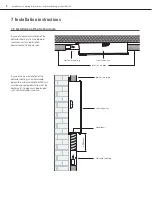
Page 8: ...case of vertical installation of the defroster heating a non flammable pipe with a minimum length of 300 mm must be connected downstream of the heater coil The pipe must be provided with non flammable...

Page 9: ...at 7831 2830 FR NK ISCHE ROHRW ERKE Gebr Kirchne r GmbH Co KG 97486 K nigsb erg Bay ern Tel 49 9525 88 2555 Fax 49 9525 88 2153 info gb_ h frae nkische de www fra enkisch e com Air Luft flow Air Luft...

Page 10: ...e rg Bayer n Tel 49 9525 88 2555 Fax 49 9525 88 2153 info gb_h fraenk ische de www frae nkische com Air Luft flow only if unit vertically mounted nur wenn Ger te vertikal montiert kun hvis aggregat mo...

Page 11: ...h Pa Airf l o w A B US B Air Luft flow B Rech tsver sion B Righ t unit unit destr a P1 P3 P4 P2 P1 P2 Pa P3 P4 m 3 Pa m 3 Eins tellw erte Cali brat i o n Cali braz i o ne 0 120 100 80 60 40 20 110 90...

Page 12: ...In addition applicable local regulations and safety provisions must be complied with 8 Maintenance and cleaning B Rech tsver sion B Righ t unit unit destr a P1 P3 P4 P2 P1 P2 Pa P3 P4 m 3 Pa m 3 Eins...

Page 13: ...resh air for apartments and residential buildings The product complies with the regulations particularly the protection requirements of the following EU directives Low Voltage Directive 2014 35 EU EMC...

Page 14: ...oped and produced for applications in so called comfort ventilation systems Any other application is considered improper and can lead to damage to the defroster heating or personal injury which the ma...

Page 15: ...Notes Installation operating instructions defroster heating profi air DN 125 15...

Page 16: ...o change without notice Cat no 5000 1340 00 01 2018 FR NKISCHE Rohrwerke Gebr Kirchner GmbH Co KG Hellinger Str 1 97486 K nigsberg Germany Phone 49 9525 88 2200 Fax 49 9525 88 92200 marketing fraenkis...

Reviews: