14
DC Wiring Connections
Input
1. Ensure that all power is off, the Listed external disconnect switch is in the off position, and that the following wires are properly
identified with polarity and/or ground marks:
• Cable from the PV array to the external DC disconnect switch.
• Cable from the external DC disconnect to the Fhoton™ Drive.
• Ground wire, insulated, green or green with yellow stripe.
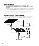
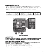
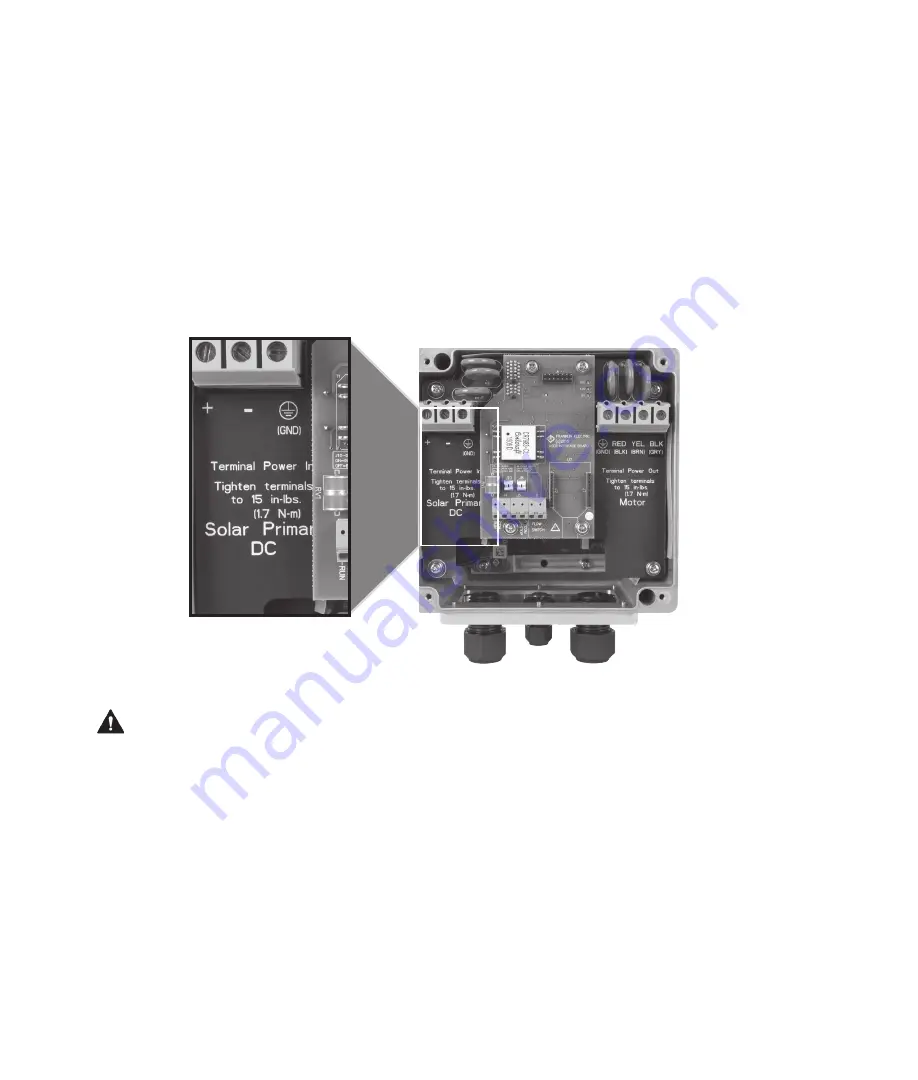
2. Connect the cables from the external DC disconnect to the “Solar Primary DC” terminal block. Connect conductor to
+ terminal, conductor marked – to – terminal, and green ground conductor to “GND” terminal (see Figure 4). Tighten terminal
block screws to 15 in-lbs. ( 1.7 N-m) torque. Use Copper Conductors Only. Use cables rated 75 °C only.
Connect the DC input of the Fhoton™ Drive only to a Photovoltaic (PV) solar array using a Listed disconnect switch.
• Model 58101300086: Suitable For Use On A Circuit Capable Of Delivering Not More Than 5,000rms Symmetrical Amperes, 300VDC
Maximum.
• Model 58101420086: Suitable For Use On A Circuit Capable Of Delivering Not More Than 5,000rms Symmetrical Amperes, 420VDC
Maximum.
• Model 581011100984: Suitable For Use On A Circuit Capable Of Delivering Not More Than 5,000rms Symmetrical Amperes, 110VDC
Maximum.
The integral motor solid-state short circuit protection in this drive does not provide Branch Circuit Protection. Branch Circuit protection
must be provided in accordance with the National Electrical Code, and any applicable local electrical codes.
CAUTION
Figure 4: DC Wiring Connection
Summary of Contents for Fhoton 2
Page 1: ...Installation Guide FHOTON Drive ...
Page 2: ...2 ...
Page 29: ...Guía de instalación Dispositivo FHOTON ...
Page 30: ...2 ...
Page 57: ...Guide d installation FHOTON DRIVE ...
Page 58: ...2 ...
Page 85: ...Guia de instalação CONTROLADOR FHOTON ...
Page 86: ...2 ...


