17
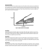
For retrofit application, make sure to check integrity of power and motor leads. This requires measuring the insulation resistance with
the suitable megohmmeter. Reference the Franklin Electric AIM for correct measures. (See Table 4. Page 20 Motor Specifications)
Control Switch Wiring Connections (Optional)
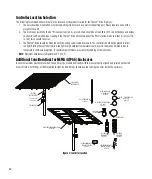
The Fhoton™ Drive can be operated with control switches to control the ON/OFF pumping range. Use a normally closed low-voltage
control switch with a contact rating suitable for instrumentation use (i.e. Max: 24 V 15mA):
1. Connect the cables from the “STOP” control switch to the Terminal Block labeled “STOP”.
2. Connect the cables from the “RUN” control switch to the Terminal Block labeled “RUN” (Figure 8).
3. If disconnecting control switch wires, use small flathead screwdriver, or similar tool, to press the orange button above the wire.
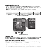
Pump/Motor Wiring Connections
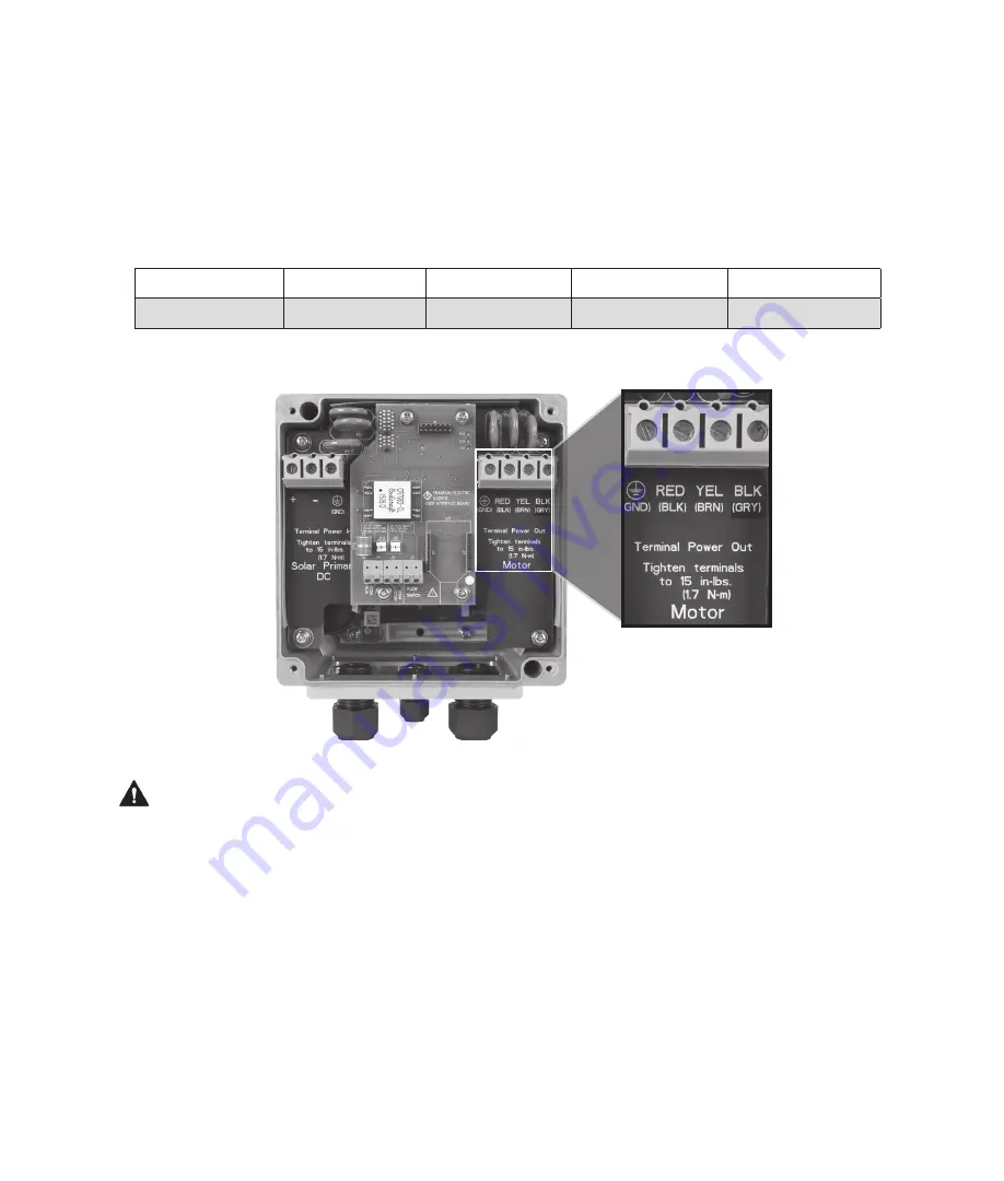
Connect the cables from the Pump/Motor Assembly to the “MOTOR” Terminal Block. Match motor cable colors to terminals marked
RED, YEL, and BLK, and connect the green ground lead to the GND terminal (Figure 6). Tighten terminal block screws to 15 in-lbs. (1.7
N-m) torque. Use Copper Conductors Only. Use cables rated 75 °C only.
NOTE:
For motors with international leads, use Table 3 for motor lead color information to ensure correct installation.
US
Black (BLK)
Ground (GND)
Red (RED)
Yellow (YEL)
International
Gray (GRY)
Black (BLK)
Brown (BRN)
Ground (GND)
Table 3: US and International Wire Color Chart
CAUTION
Figure 6: Motor Wiring Connection
Summary of Contents for Fhoton 2
Page 1: ...Installation Guide FHOTON Drive ...
Page 2: ...2 ...
Page 29: ...Guía de instalación Dispositivo FHOTON ...
Page 30: ...2 ...
Page 57: ...Guide d installation FHOTON DRIVE ...
Page 58: ...2 ...
Page 85: ...Guia de instalação CONTROLADOR FHOTON ...
Page 86: ...2 ...


