7
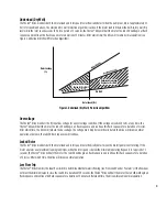
The Franklin Electric Fhoton™ Drive is designed to be part of a system that consists of:
A. Solar Array (not included)
B. DC Rated Disconnect - Per applicable codes
C. Fhoton™ Solar Drive
D. Standard Pump and Motor
E. Flow Switch (with sensor cable)
F. Control Switches (optional, not included)
Pump Check Valve Requirements
NOTICE: In order to ensure maximum system reliability and water delivery, check valves must be installed in the drop pipe.
The first check valve must be installed at the pump (the 5-25 GPM (18-70 LPM) pumps have a built in check valve in the pump
discharge) and additional check valves should be installed every 100 ft. (30 m.) of vertical pipe after the pump. (See the pump
owner’s manual for additional information.)
7
(OPEN)
(CLOSED)
(OPEN)
(CLOSED)
Two Level Control Switch Operation
30A - 2 Pole DC
Rated Disconnect
Flow Switch
Level
Control
“Stop”
Level
Control
“Run”
DC Power
Solar PV Array
Pump/Motor
Fhoton Drive
SOLAR INVERTER PUMP CONTROLLER
D
E
B
C
A
Figure 1: Fhoton™ Drive System
F
Summary of Contents for Fhoton 2
Page 1: ...Installation Guide FHOTON Drive ...
Page 2: ...2 ...
Page 29: ...Guía de instalación Dispositivo FHOTON ...
Page 30: ...2 ...
Page 57: ...Guide d installation FHOTON DRIVE ...
Page 58: ...2 ...
Page 85: ...Guia de instalação CONTROLADOR FHOTON ...
Page 86: ...2 ...


