33
Pressure Input Selection (DIP SW1 — Position 5)
Ensure that the drive is configured for the type of pressure transducer or sensor being used:
•
If using a 4-20 mA 100 PSI pressure transducer (included), DIP SW1 Position 5 must be in the XDCR
(down) position.
•
If using a standard pressure sensor, DIP SW1 Position 5 must be in the PS (up) position.
Adjusting Pressure Setting
IMPORTANT:
Monitor pressure gauge during initial startup to ensure system does
not over-pressurize.
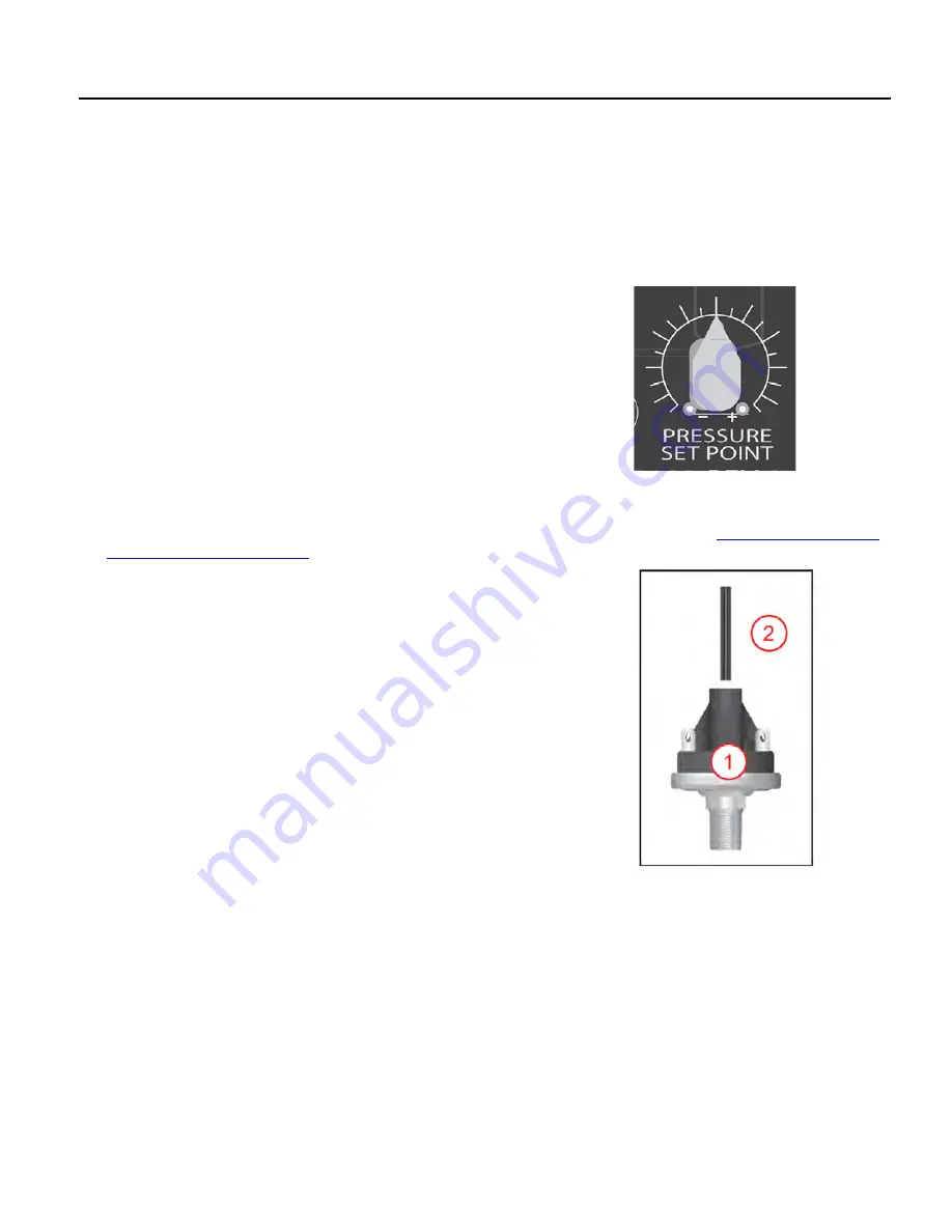
PPrreessssuurree TTrraannssdduucceerr:: When using the 100 PSI pressure transducer, the desired
system pressure is set by using the pressure setpoint adjustment knob. The knob is
factory set to 50 PSI and is adjustable from 5 to 95 PSI in 5 PSI increments. Refer
to the indicator lines surrounding the switch and the corresponding legend printed
on the shield when setting the desired pressure setpoint.
The pressure setpoint must be adjusted with the drive powered OFF. When the
drive is powered ON, the screen will display the active system pressure.
NOTE:
This knob is only compatible with the default 4-20 mA 100 PSI pressure transducer. If using a pressure transducer with a
different range, DIP Switch 1 – Position 1 must be in the O
ON
N (up) position and the Pressure Transducer Type, Pressure Trans-
ducer Range, and Pressure Setpoint parameters must be configured using the mobile app. Refer to
the FE Connect App” on page 44
.
PPrreessssuurree SSeennssoorr:: The sensor (1) is preset at the factory to 50 psi (3.4 bar), but
can be adjusted by the installer using the following procedure:
•
Remove the rubber end-cap.
•
Using a 7/32” Allen-wrench (2), turn the adjusting screw clockwise to increase
pressure and counter-clockwise to decrease pressure. The adjustment range is
between 25 and 80 psi (1.7 and 5.5 bar).
NOTE:
1/4 turn = approximately 3 psi (0.2 bar).
•
Replace the rubber end cap.
•
Cover the pressure sensor terminals with the rubber boot provided. Do not
place boot in direct sunlight.
IMPORTANT:
Do not exceed the mechanical stop on the pressure sensor.
When the drive is powered ON, the display will show motor speed rather than the
active system pressure.
Summary of Contents for SubDrive 15
Page 1: ...S SU UB BD DR RIIV VE E C CO ON NN NE EC CT T Owner s Manual ...
Page 14: ...14 ...
Page 22: ...22 ...
Page 30: ...30 ...
Page 36: ...36 ...
Page 40: ...40 ...
Page 56: ...56 ...
Page 62: ......
Page 63: ...ESPAÑOL ES franklinagua com SUBDRIVECONNECT Manual para propietarios ...
Page 70: ...8 ...
Page 78: ...16 ...
Page 84: ...22 ...
Page 88: ...26 ...
Page 96: ...34 ...
Page 102: ...40 ...
Page 106: ...44 ...
Page 128: ......
Page 129: ...franklinwater com FRANÇAIS FR SUBDRIVECONNECT Manuel du propriétaire ...
Page 136: ...8 ...
Page 144: ...16 ...
Page 150: ...22 ...
Page 154: ...26 ...
Page 162: ...34 ...
Page 168: ...40 ...
Page 172: ...44 ...
Page 194: ...REMARQUES ...
Page 195: ...REMARQUES ...
Page 196: ......


