34
Performance Settings
NOTICE
Risk of damage to drive or water system can occur due to improper adjustment
or settings.
•
System behavior should be monitored when adjusting any of these settings to ensure
proper operation.
•
Confirm that an adequate pressure relief valve is included in the system.
Drawdown Feature (FE Connect App Only)
When using a pressure transducer, an optional “cut-in” pressure can be set to allow for more water to
be drawn from the tank. For example, a system setpoint pressure of 50 PSI and a cut-in pressure of 30
PSI would cause the drive to maintain system pressure at 50 PSI when running; however when the sys-
tem is idle, the drive will not start the motor until the system pressure drops below 30 PSI.
Refer to
“Drive Configuration Using the FE Connect App” on page 44
to activate and set the cut-in
pressure.
System Response (DIP SW3)
When using a pressure transducer with a surface pump application, the system response can be adjusted
as follows:
System Response
SW3–3 FAST (VR, MH, or DDS)
SW3–4 MED
SW3–5 SLOW (BT04)
Proportional Gain (P)
70
53
35
Integration Time (I)
0.2
.02
.02
Ramp Rate (R)
90
50
20
Select one DIP switch for preset FFA
ASSTT, M
MEEDD, or SSLLO
OW
W system response parameters. Selecting more than
one switch will result in an Invalid DIP Switch Fault (F24). If no selection is made, the system will default
to SSLLO
OW
W (no fault occurs).
M
Miinniim
muum
m FFrreeqquueennccyy:: In surface pump applications, placing DIP SW3 Position 6 in the O
OFFFF (down) po-
sition will set the minimum output frequency to 30 Hz (default). Move the switch to the O
ON
N (up) position
to set the minimum output frequency to 15Hz. Refer to
“Drive Configuration Using the FE Connect App”
for more precise settings.
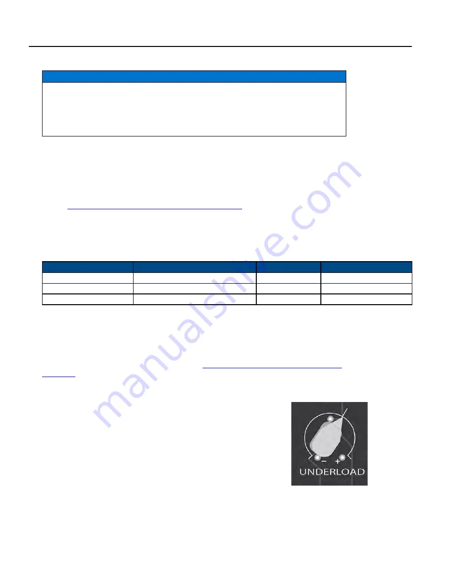
Underload Sensitivity
The drive is configured at the factory to ensure detection of Underload faults in a
wide variety of pumping applications. In rare cases (as with certain pumps in shal-
low wells), this trip level may result in unnecessary faults. If the pump is installed
in a shallow well, activate the drive and observe system behavior. Once the system
begins to regulate pressure, check operation at several flow rates to make sure the
default sensitivity does not cause false Underload trips.
If it becomes necessary to adjust the Underload trip level, remove power and wait
five minutes for the controller to discharge. Once the internal voltages have dissi-
pated, locate the Underload Potentiometer on the upper-right corner of the User
Interface Board.
SShhaalllloow
w SSeett:: If the pump is installed in an extremely shallow (i.e. artesian) well and the system continues to trip, then adjust
the Underload Potentiometer counter-clockwise to a lower sensitivity setting. Check the Underload trip level and repeat as
necessary.
Summary of Contents for SubDrive 15
Page 1: ...S SU UB BD DR RIIV VE E C CO ON NN NE EC CT T Owner s Manual ...
Page 14: ...14 ...
Page 22: ...22 ...
Page 30: ...30 ...
Page 36: ...36 ...
Page 40: ...40 ...
Page 56: ...56 ...
Page 62: ......
Page 63: ...ESPAÑOL ES franklinagua com SUBDRIVECONNECT Manual para propietarios ...
Page 70: ...8 ...
Page 78: ...16 ...
Page 84: ...22 ...
Page 88: ...26 ...
Page 96: ...34 ...
Page 102: ...40 ...
Page 106: ...44 ...
Page 128: ......
Page 129: ...franklinwater com FRANÇAIS FR SUBDRIVECONNECT Manuel du propriétaire ...
Page 136: ...8 ...
Page 144: ...16 ...
Page 150: ...22 ...
Page 154: ...26 ...
Page 162: ...34 ...
Page 168: ...40 ...
Page 172: ...44 ...
Page 194: ...REMARQUES ...
Page 195: ...REMARQUES ...
Page 196: ......


