6
Setup and Operation
Set up the console so that the alarms operate properly:
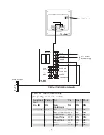
1. Identify the relay that is being used to activate the overfill alarm equipment.
2. Navigate to the setup programming of that relay.
3. Confirm that the relay is programmed according to the following:
• Name: Overfill Alarm Relay (or similar).
• Enabled: Yes
• Type: Alarm
• Polarity: Normal
• Logic: OR Logic
• Physically Wired As: Normally Open
• Number of inputs: 0
NOTE:
If you have a legacy console, refer to the associated programming manuals for specific information.
4. Make sure the rule activates the overfill alarm equipment when a HIGH or HIGH HIGH tank alarm occurs. Go to
the Rules section of programming:
• Rule: Overfill Alarm Activate (or similar)
• Name: Overfill Alarm Activate (or similar)
• Enabled: Yes
• Events
• Event: Type Alarm Occurred
• Category: FMS
• Device: Tank
• Device ID: Any
• Code: High high product level
Actions
• Action Type: Relay
• Module: Power Supply Module
• Channel: Overfill Alarm Relay
• Action: One Pulse
• Duration: 2
NOTE:
Legacy consoles that do not have the One Pulse option must incorporate two seperate actions. One action to
activate the relay, the second action to deactivate the relay.
NOTE:
Verify that the code you select sounds the alarm at the correct volume/limit set for each tank.
NOTE:
Verify that the code you select refers to the correct High High or High product threshold. You can confirm the units
in which the High and High High thresholds are measured under Fuel Management Systems/High Product Limit.
5. Force the tank into the High or High High Alarm by manually raising the product float beyond the threshold and
confirming the Overfill alarm sounds. Press the acknowledge button on the TS-RK to silence the alarm.
Testing the Alarm Wiring
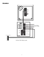
Use the following procedure to verify that the tank Overfill Alarm is wired correctly. If the Setup and Operation procedure
does not produce an Overfill Alarm, use the following procedure to verify that the issue is not caused by improper wiring.
1. Go to System/Diagnostic/Relay Status.
2. Select the Activate/Deactivate checkbox for the Overfill Alarm Relay (or a similar relay). The Active indicator
becomes GREEN for the associated relay.
3. Make sure the Overfill Alarm is activated.
a. If the Overfill Alarm is activated, the wiring is correct. Clear the Overfill Alarm Relay checkbox to deactivate
the relay. Press the acknowledgment button on the TS-RK to silence the alarm.
b. If the Overfill alarm is not activated, there is an issue with the wiring. Clear the Overfill Alarm Relay checkbox
to deactivate the relay. Consult the TS-RA1, TS-RA2, TS-RK installation manual for information about proper
wiring.
NOTE:
If you have a legacy console, refer to the associated programming manuals for information about manually
activating relays.
Summary of Contents for TS-RA1
Page 8: ...FFS 2018 000 1027 r7...

