T
it
le
Franklin Home Power User Manual
Date
August 10, 2021
Doc. No.
FD21081001
Revision
V01
© 2021. FranklinWH Technologies Co., Ltd.
Page 13 Total 31
3.2 aPower
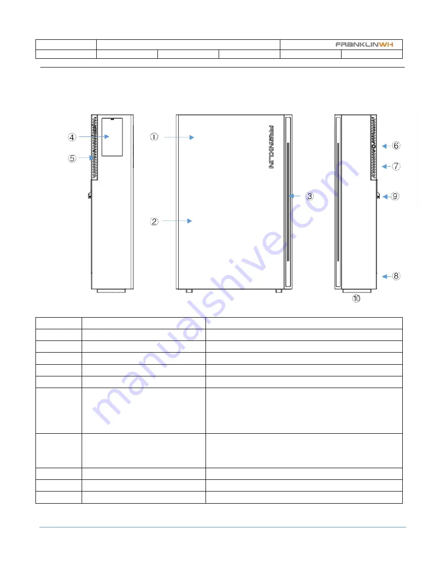
The below shows the aPowers appearance and components and features.
Figure aPower appearance and components
Items
Descriptions
Remarks
1
Power converters system (PE) inside
It can be replaced by maintenance required
2
Battery full pack with BMS inside
3
LED indicator
Indicates the unit status
4
Wiring compartment
Provides the connection ports to aGate
5
Vented grille
There have 3 plates on the left, right, and top.
6
aPower on/off button
Default the button off during shipping and storage. It is required
to push the button down a little as on to power on the aPower and
LED will be lighted after the aPower is installed completely until
emergency stop when maintenance or replacement.
7
Air vent outlet
At the upper of the unit back
The battery pack has a heatsink and fans cooling at the unit back
The PE unit has a heatsink at
the
top of the unit.
8
Air vent inlet
At the back bottom
9
Mounting hook
10
Legs support


