Operation and Maintenance Manual, OnyX Sky Heat Recovery Units, 2022/01
Frapol Sp. z o.o. reserves the right to introduce changes without any prior notice.
Page
33
5.6.8
Connection of differential pressure transmitters to Constant Flow module
NOTE
Before works related to the connection of differential pressure transmitters, the main power supply of the
air handling unit must be disconnected
Preparation for assembly
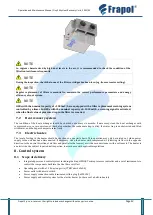
First, disassemble the masking electrical boxes with insulated connection and pressure wires. The cables must be
stripped of insulation. The cable ends should be supplemented with insulated clamp sleeves. In place of electrical boxes,
the supplied ecoPress differential pressure transmitters should be installed by locating the connectors of the differential
pressure converter downwards.
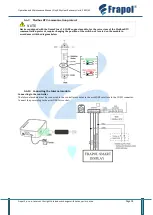
Electrical connection
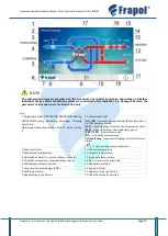
After passing the cables through the choke, make the electrical connection according to the diagram below:
Connection of pressure hoses
Depending on the device model, one or two pressure hoses may be present in the masking electrical box. The cables
should be connected to the stub pipe
or
as described on the cable.
Setting the working range of the differential pressure transmitter
Depending on the AHU model, set the appropriate working range of the differential pressure transmitter. The setting is
made by the appropriate configuration of jumpers. The configuration of jumpers for a specific operating range is
described on the transducer cover.
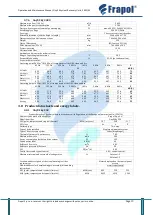
AHU model
Differential pressure transmitter working range
Type of transducer
OnyX Sky 250
500 Pa
ecoPress 500
OnyX Sky 400
OnyX Sky 500
OnyX Sky 750
1000 Pa
ecoPress 2500
OnyX Sky 1000
OnyX Sky 1500
OnyX Sky 3000
ecoPress 500
ecoPress 2500
Configuration in Frapol SMART control panel
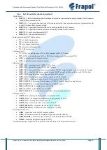
In order to start the Constant Flow module in the device, enter the Installer menu (point 8.15)
[Panel Basic]
Installer Menu
→
CF Mode
→
Enabled
[Panel Advanced]
Installer Menu
→
General Settings
→
CF Mode
→
Enabled

