Operation and Maintenance Manual, OnyX Sky Heat Recovery Units, 2022/01
Frapol Sp. z o.o. reserves the right to introduce changes without any prior notice.
Page
40
5.8.3
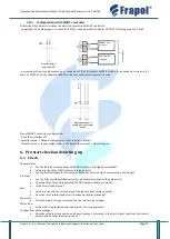
Configuration with SMART controller
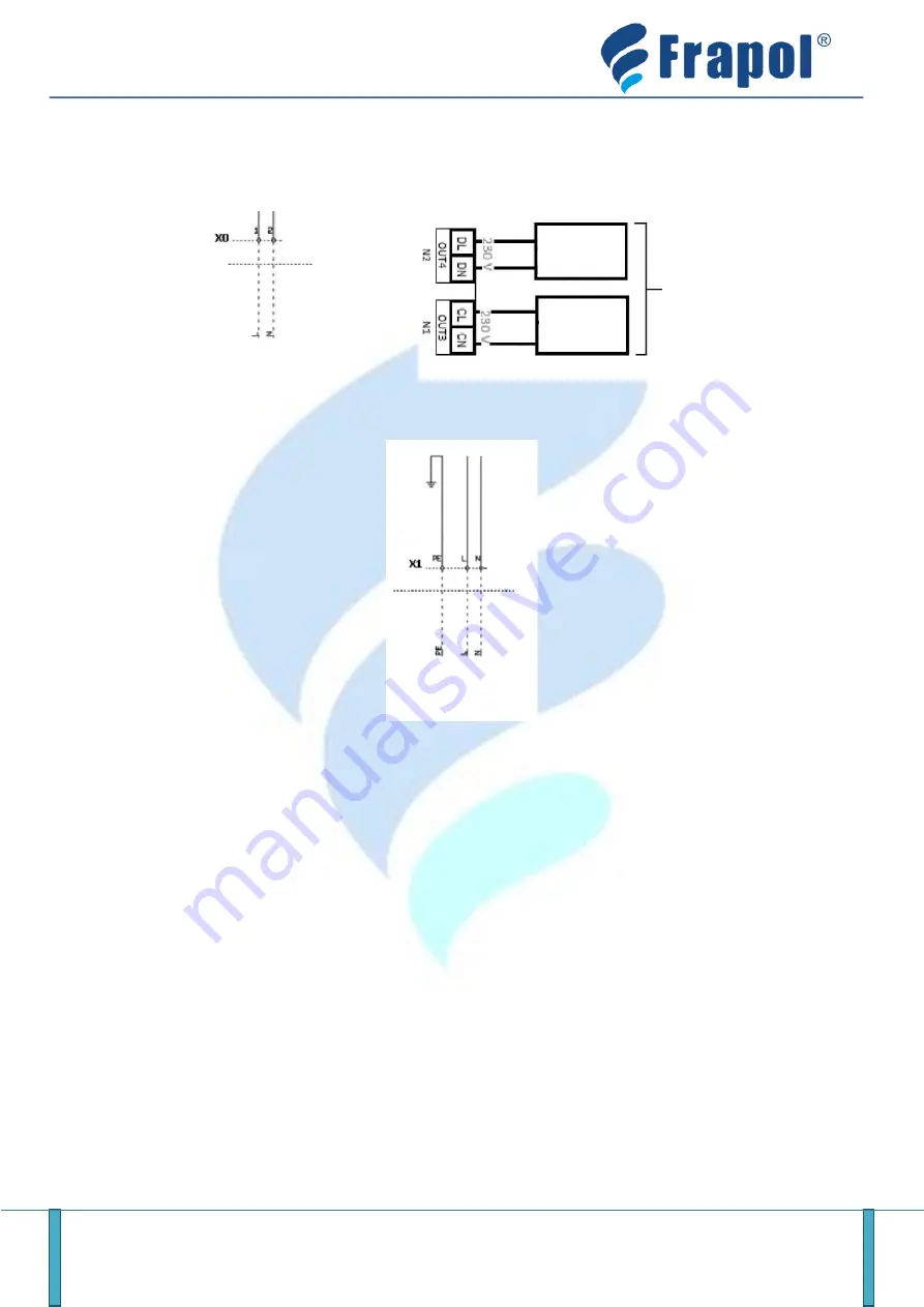
Follow the steps below to activate the electric heater in the SMART controller:
- supply the controlling signal
–
connect the
X0[1,2]
connector with
Pre-heater OUT3[CL,CN]
using wire 2x1.5 mm
2
- power supply from an external source to connector
X1[PE,L,N]
(heater 1x230 V) with a three-conductor wire min. 1.5
mm
2
, or
X1[PE,L1,L2,L3]
(heater 3x400V) with a four-conductor wire min. 2.5 mm
2
Frapol SMART controller configuration:
- Turn the controller off
-
Installer menu → Outputs configuration → Pre
-
heater → Electric
-
Installer menu → Input configuration → Pre
-
heater thermostat → Normally open
6.
Pre-start check and starting-up
6.1
Check
General status:
•
Are the individual components of the HRU properly and tightly assembled?
•
Is the interior of the HRU free from foreign objects?
•
Are the flexible flanges for connecting ventilation ducts too tight, compressed, or damaged?
Air filters:
•
Are the filter cartridges fitted correctly and securely fastened in the guide rails?
•
Does the filter class and type match the HRU documentation provided?
•
Is the filter cloth not torn?
Fan:
•
Is the interior and the surrounding of the fan free from foreign objects?
•
Does the rotor rotate freely after it has been activated manually?
Fan motor:
•
Does the supply voltage correspond to the rated motor voltage?
Water trap:
•
Is the water trap installed and connected to the sewage system?
Counter-flow heat exchanger
•
Does the actuator close and open a bypass damper, according to the force signal sent from the control
system, and not the other way around?
Control routed
from the HRU
REHEAT COIL
(<1000 W)
control signal
PRE-HEATER
< 1000W
Single-phase power
supply from an external
source


