Operation and Maintenance Manual, OnyX Sky Heat Recovery Units, 2022/01
Frapol Sp. z o.o. reserves the right to introduce changes without any prior notice.
Page
47
NOTE
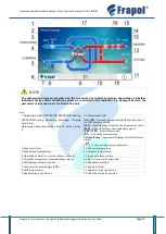
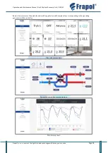
The automation diagrams presented on the screen may be subject to change, depending on whether
individual devices of the ventilation system are connected to the controller, e.g., dampers, heaters: the
parameter values shown are for illustration only.
Key:
1. Adjustment mode: OPERATION, OPERATION-Heating,
OPERATION-Cooling, Defrosting, Exchanger Cleaning,
Ventilation.
Main modes: Downtime, Mode 1, Mode 2, Mode 3, Mode
4
10. Information field:
[
R1
], [
R2
]
–
flow rate demand threshold (hood mode) or
air filter pressure switch;
[
SAP
]
–
signalling input from the fire alarm control unit;
[
ECO
]
–
signal input from the annunciator panel;
[
TR1
], [
TR2
]
–
heater thermostat;
[
Q1
]
–
air quality measurement;
Active alarms
–
if pressed, it displays a list of all current
alarms
[
]
–
active positive pressure function.
2. Exhaust air flow.
11. Exhaust temperature.
3. Exhaust vent temperature.
12. Setpoint temperature.
4. Operation of electric or water primary air heater.
13. Air supply temperature.
5. Air intake temperature (external temperature).
14. DX or water cooler operation.
6. GHE damper actuator position.
15. Reheater operation.
7. Ground-air heat exchanger (GHE).
16. Supply air flow.
8. GHE temperature.
17. Bypass actuator position 2.
9. Bypass actuator position 1.
18. Mixer box actuator position.


