12
FTEC11-01
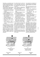
I principali criteri generali che stanno alla base
di una buona progettazione delle linee frigorifere
sono:
•
per tutte le linee
-
pendenza di almeno 1% nella direzione
del flusso
-
velocità del refrigerante tale da garantire
il trascinamento del lubrificante senza
eccessive perdite di carico
•
per le linee di aspirazione e compressione
-
un sifone alla base di ogni colonna con
flusso ascendente
-
un sifone ogni 3
÷
4 metri di colonna
con flusso ascendente
-
all’uscita dell’evaporatore, un montante
(con sifone alla base) che, prima di
collegarsi al compressore, superi il
colmo dell’evaporatore stesso.
FRASCOLD suggerisce tale soluzione
anche per impianti con sistema “pump-
down”, così da evitare ritorni di liquido
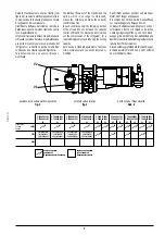
The main general principles which are the basis
of a good refrigerating lines design are:
•
for every line
-
slope of at least 1% in the direction of
flow
-
refrigerant velocity to allow the
refrigerant entrainment without
excessive pressure drop
•
for suction and discharge lines
-
one trap at the base of each column
with rising flow
-
one trap each 3
÷
4 meters of column
with rising flow
-
at the evaporator outlet one riser
(with trap at the base) that, before going
to the compressor, exceeds the
evaporator full.
FRASCOLD suggests to apply this
principle with “pump-down” system
also to avoid the liquid refrigerant to
flood the suction side of the compressor
Dabei ist zu verhindern, daß flüssiges Kältemittel
während der Stillstandsphase des Verdichters
zum Verdichter gelangt.
Die wichtigen Merkmale einer guten
Rohrleitungsauslegung sind:
•
Für alle Leitungen
-
Mindestens 1% Gefälle in Flußrichtung
-
Ausreichend Kältemittelgeschwindigkeit
zur Vermeidung eines hohen
Druckabfalles
•
Für Saug- und Druckleitungen
-
Eine Falle am unteren Ende von
Steigleitungen
-
Eine Falle nach 3-4 Metern bei höheren
Steigleitungen
-
Am Verdampferausgang eine Falle mit
anschließender Steigleitung über die
Gesamthöhe des Verdampfers hinaus
-
FRASCOLD empfiehlt im Übrigen die
„Pump-Down“ Schaltung des Systems
um eine Überflutung der
2
1
3
4
5
6
7
10
8
9
WO
WI
WO
WI
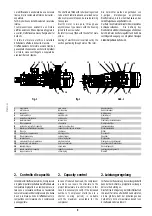
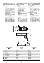
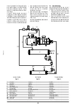
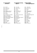
1
compressore
compressor
Verdichter
2
condensatore
condenser
Verflüssiger
3
evaporatore
evaporator
Verdampfer
4
filtro deidratore
filter drier
Filtertrockner
5
valvola elettromagnetica
solenoid valve
Magnetventil
6
spia di passaggio
sight glass
Schauglas
7
valvola termostatica
thermostatic expansion valve
Expansionsventil
8
linea di compressione
discharge line
Druckleitung
9
linea del liquido
liquid line
Flüssigkeitsleitung
10
linea di aspirazione
suction line
Saugleitung
WI
ingresso acqua
water inlet
Wassereintritt
WO
uscita acqua
water outlet
wasseraustritt
raffreddatore di liquidi
liquid chiller
Flüssigkeitskühlsatz
fig. 10
fig. 10
Abb. 10

