background image

14

FTEC11-01

Si suggerisce di adottare tutti gli accorgimenti
necessari per garantire che, entro 10 secondi
dall’avviamento del compressore, venga
raggiunta una differenza di pressione di almeno
4 bar tra compressione e aspirazion).
In impianti con evaporatore allagato, è necessario
installare una valvola elettromagnetica abbinata
a una valvola regolatrice della pressione del
carter; deve essere installata a un  livello
superiore a quello di uscita della linea di
aspirazione e deve chiudersi all’arresto del
compressore.
In impianti con temperature di evaporazione alte
e condensatore remoto a installazione esterna,
si può verificare la migrazione di refrigerante in
occasione di basse temperature ambiente.
Anche negli impianti con condensatore e/o
evaporatore multi-circuito, si può manifestare la
migrazione di refrigerante verso l’evaporatore.
Adottare appropriate soluzioni, da valutare caso
per caso, per evitare tale situazione.
Impianti dotati di sbrinamento con gas caldo
oppure con valvola di inversione del ciclo
frigorifero, richiedono soluzioni da valutare caso
per caso per proteggere il compressore dai danni
causati da ritorni di liquido e aumentata
migrazione di olio.
L’installazione di un accumulatore di aspirazione
eviterà ritorni di liquido al compressore.
Durante l’inversione del ciclo frigorifero, una
temperatura dell’olio maggiore di 30

÷

40K di

quella di condensazione eviterà la migrazione di
lubrificante causata dalla rapida diminuzione di
pressione all’interno del separatore.
Per impedire riduzioni di pressione nella linea di
compressione, si raccomanda di installare una
valvola regolatrice della pressione di
condensazione sulla linea di compressione.
In particolari condizioni operative, è possibile
arrestare per un breve periodo il compressore
prima dell’inversione del ciclo frigorifero, quindi
riavviarlo non appena le pressioni in aspirazione
e compressione sono equalizzate.
In tale caso, è necessario verificare che entro
10 secondi dall’avviamento, si stabilisca la
minima differenza di pressione (4 bar) tra
compressione e aspirazione.

7.1

Iniezione di liquido

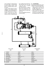
La valvola di iniezione di liquido deve essere
dotata di speciale carica termostatica adatta ad
operare con le alte temperature di scarico del
compressore.
Il bulbo della valvola di iniezione deve essere
messo in contatto con il tubo di compressione del
compressore, alla distanza di 10

÷

15 cm dal

rubinetto di compressione.
La zona di tubo a contatto con il bulbo deve
essere ben pulita quindi ricoperta di pasta
conduttrice; una volta posizionato, il bulbo deve
essere strettamente fissato alla tubazione, il tutto
deve essere ricoperto di materiale
termo-isolante.

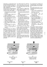
solenoid valve combined with a crankcase
pressure regulating valve; it must be installed in
a point higher than the suction outlet and is
closed during compressor standstill.
Cooling systems with low evaporating
temperature and outdoor condenser installation,
refrigerant migration can occours when the
ambient temperature is very low.
Refrigerant migration to the evaporator can occours
in multi-circuit condenser and /or evaporator;
perform suitable procedures to avoid it.
Systems with reversing cycle valve or hot gas
defrost, individual solution must be applied
to protect the compressor against liquid
slugging and increased oil migration.
The installation of a suction accumulator is
recommended to protect the compressor against
damages caused by liquid slugging.
During reversing cycle mode, the fast pressure
reduction in to the lubricant separator causes
the oil migration; keep the oil temperature
30

÷

40K higher than condensing temperature

to avoid lubricant migration.
To prevent low pressure in the discharge line,
the installation of a discharge pressure regulating
valve is strongly recommended; the valve has
to be installed on the discharge line.
Under certain operative conditions it is possible
to stop the compressor for a short period before
the reversing cycle mode; as soon as the suction
and discharge pressures have been equalized,
the compressor can be started again.
With this procedure, verify that the minimum
pressure difference (4 bar) between suction and
discharge takes place no later than 10 second
after the compressor starting.

7.1

Liquid injection

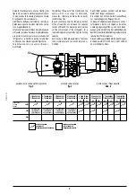
The liquid injection valve has to be equipped
with thermostatic charge specific to operate with
discharge temperature.
The contact area of the bulb of the liquid injection
valve bulb is on the compressor discharge line,far
10

÷

15 cm from the discharge valve.

Brush the contact area of the bulb, then apply
heat transfer paste, place the bulb and fasten it
to the pipe; wrap all with thermal insulator.
Draw line for liquid refrigerant comes from the
horizontal section of main liquid line, then it
directs downward.
Complete the liquid injection line with filter drier,
sight-glass, and solenoid valve to shut-off the
flow when compressor stops.
Contact FRASCOLD Technical Department or
use our software of screw compressors
performance calculation for the correct matching
between model of compressor and model of
liquid injection kit selected by FRASCOLD.

7.2

Unloading start

The starting of a screw compressor requires a
very low starting torque because the following
reasons:

innerhalb 10 Sekunden nach dem Verdichterstart
zu erreichen.
Bei Anlagen mit überfluteten Verdampfern, ist
ein Magnetventil kombiniert mit einem
Gehäusedruckreglerventil, erforderlich.
Es soll direkt oben am Saugleitungsaustritt
eingebaut werden und es schließt sich bei
Verdichterstillstand.
Bei Anlagen mit hohen
Verdampfungstemperaturen und
Verflüssigeraufstellung im Freien, kann die
Kältemittelverlagerung bei niedrigen
Außentemperaturen sich ereignen.
Auch bei Anlagen mit Mehrkreis-verflüssigern
und/oder -verdampfern besteht die Gefahr von
Kältemittelverlagerung in den Verdampfer.
Um diese Situation zu vermeiden, bitte wenden
geeigneten Lösungen an, die anfallweise
eingeschätzt werden sollen.
Anlagen mit Heißgasabtauung oder mit
Kreislaufumkerungsventil erfordern anfallweise
schätzbare Lösungen, um den Verdichter vom
Schaden für Flüssigkeitsschläge und erhöhte
Ölverlagerung zu schutzen.
Die Installation einem Saugakkumulator wird
Flüssigkeitsschläge vermeiden.
Während die Kreislaufumkehrung, soll die
Öltemperatur höher von 30 

÷

 40K als der

Verflüssigungstemperatur liegen, um die
Schmiermittelverlagerung zu vermeiden.
Ein Druckregler über den Druckleitung wird
empfohlen, um Druckabsenkungen zu verhindern.
Unter besonderen Betriebsbedingungen, ist es
möglich den Verdichter vor der
Kreislaufumkehrung kurz anzuhalten und nach
Druckausgleich wieder zu starten.
In diesem Fall, ist es erforderlich zu prüfen, daß
innerhalb 10 Sekunden nach dem
Verdichterstart, der Mindestdruckdifferenz (4 bar)
sich festsetzt.

7.1

Flüssigkeitseinspritzung

Die Flüssigkeitseinspritzventil soll mit spezielle
thermostatische Füllung komplett sein, geeignet
für die hohe Verdichtersdrucktemperaturen.
Der Ventilfühler soll an der Druckgasleitung,
10 

÷

 15 cm vom Druckabsperrventil entfernt.

Diese Zone soll sortfältig sauber und mit
Wärmeleitpaste benetzten sein.
Der Fühler ist mit Rohrschellen zu befestigen
und zu isolieren.
Die Abziehungsleitung soll mit einem
horizontalen Hauptleitunsabschnitt verbunden
sein aus zunächst nach unten geführt werden
Die Flüssigkeitseinspritzleitung soll komplett mit
Trocknerfilter, Schauglas und Magnetventil um der
Fluß bei den Verdichterhaltung auszuschalten.
Fragen Sie an unsere Technische Abteilung
oder benutzen die software der
Schraubenverdichtersleistungs für die Korrekte
Zuordnung von Verdichter und
Flüssigkeitsspritzung Satz von FRASCOLD
gewählt.

Summary of Contents for C-TSH Series

Page 1: ...C TSH COMPRESSORICOMPATTIADOPPIAVITE COMPACTTWINSCREWCOMPRESSORS KOMPAKTDOPPELSCHRAUBENVERDICHTER Guida operativa Application guide Projektierungshandbuch 2003 11 01...

Page 2: ...eavviso FRASCOLD SpA reserves the right to change at any time specifications or design without notice and without incurring obligations FRASCOLD SpA beh lt sich das Recht vor Spezifikationen oder Ausf...

Page 3: ...pressor fixing 4 Lubrication 4 1 Built in oil separator 4 2 Oil cooling 5 The lubricant 5 1 Lubricant data 5 2 Recommendations 5 3 Lubricant mixing oil replacement 6 Compressor installation piping 6 1...

Page 4: ...ainly due to exclusive design of screw profiles with a ratio 5 6 between male screw and female screw electrical motor with very high efficiency flowing through slots of the rotor suction gas is centri...

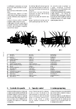
Page 5: ...Saugventil 6 scatola terminali terminal box Elektrischer Anschlu kasten 7 filtro coalescente oil demister labscheiderfilter 8 pistone del controllo di capacit capacity control piston Leistungsregelun...

Page 6: ...with no alignment problems The capacity control device consists of a three way solenoid valve directs the flow of oil in high pressure during its functioning cylinder directly connected with the sucti...

Page 7: ...ndizioni solo la rimanente porzione delle viti quella compresa tra la luce di parzializzazione e la porta di scarico opera la compressione del refrigerante a ridotta capacit volumetrica corrisponde un...

Page 8: ...nce 2 The refrrigerant passing through the demister gives an additional oil separation 4 Schmierung 4 1 Angeflanschten labscheider Der Schraubenverdichter ist charakterisiert durch ein Schmiersystem a...

Page 9: ...ug 3 DieFormundAbmessungenverursacheneine pl tzliche Verminderung der K ltemittelflu geschwindigkeitundeineheftige nderung der Flu richtung AufderInnenseitesammeltsichdasgetrennte Schmiermittel w hren...

Page 10: ...iermittel Das auf die Schrauben und die Lager eingespritzte Schmiermittel dient nicht nur zur Schmierung sondern dichtet die Schraubenprofile ab Esistsehrwichtigdas derSchmiermittelspezifische Eigensc...

Page 11: ...der s uere und verseuchte l im Anlagen mit HCFC HFC K ltemittel F r weitere Vorschl ge steht die Technische Abteilung von FRASCOLD zur Verf gung linea di uscita dell evaporatore linea di uscita dell...

Page 12: ...is principle with pump down system also to avoid the liquid refrigerant to flood the suction side of the compressor Dabei ist zu verhindern da fl ssiges K ltemittel w hrend der Stillstandsphase des Ve...

Page 13: ...la presenza di eventuali residui solidi nel sistema frigorifero Per evitare eccessive concentrazioni di refrigerante nel lubrificante durante le fasi di arresto del compressore installare il riscaldat...

Page 14: ...lation of a discharge pressure regulating valve is strongly recommended the valve has to be installed on the discharge line Under certain operative conditions it is possible to stop the compressor for...

Page 15: ...ent aus folgenden Gr nden Wenn der Verdichter anl uft ist das Tr gheitsmoment der drehenden Teile wesentlich niedriger als der Hub beim traditionellen Hubkolbenverdichter Wenn der Verdichter anh lt st...

Page 16: ...n suction and discharge The above allows screw compressor not to require an unloading start device 7 3 Economizer It is possible to increase the compressor efficiency by means an additional sucooling...

Page 17: ...icklungsstart angetrieben Bei nderung die elektrische Motorverbindung siehe Abb 13 erhaltet sich zwei verschiedene Verdichtersanlauftypen Direktanlauf D O L Teilwicklungsanlauf P W S Der Teilwicklungs...

Page 18: ...10 16 Seite 44 versehen Die Funktionen sind berwachung der maximalen Wicklungstemperatur 120 C durch sechs PTC Thermistoren die in den Statorswicklung eingeschaltet sind Dr cken MR f r die Handwieder...

Page 19: ...3 Oil heater 10 4 Accessories 10 5 Water cooled oil cooler 10 6 Air cooled oil cooler 10 7 Oil strainer 10 8 Flow switch 10 9 Electronic module for flow switch 10 10 Solenoid valve 10 11 Oil sight gla...

Page 20: ...maler Betriebstrom A LRA Corrente a rotore bloccato A corrente a rotore bloccato con collegamento D O L Locked rotor current A locked rotor current with connection D O L Anlaufstrom A Anlaufstrom mit...

Page 21: ...compressore Compressor model Verdichtermodel 10 4 Accessori Accessories Zubeh r composto da filtro olio flussostato valvola elettromagnetica indicatore di passaggio modulo elettronico per flussostato...

Page 22: ...eintemperatur 95 C temperatura uscita olio oil outlet temperature laustrittemperatur 70 C fattore di sporcamento fouling factor Verschmutzungsfaktor 0 Attacchi Connections Anschl sse 1 ingresso olio o...

Page 23: ...ure laustrittstemperatur 70 C Dimensioni Dimensions Abmessungen A 50 5 mm 50 5 mm 50 5 mm B 42 5 mm 42 5 mm 52 5 mm C 619 mm 600 mm 600 mm OIL attacchi a saldare solder connections L tanschl sse 22 mm...

Page 24: ...zione elettrica supply Elektroanschlu 220 230 V 50 60 Hz potenza assorbita input power Stromaufnahme 10 W grado di protezione safety class Schutzklasse IP65 attacchi a saldare solder connections L tan...

Page 25: ...ce on nominal values 5 after 72 hours run in tc condensing temperature Die gezeigten Leistungswerte basieren auf den folgenden Bedingungen Sauggas berhitzung 10K Tolleranzbereich 5 dann 72 Stunden von...

Page 26: ...onomizer senza economizzatore without economizer ohne Economizer con economizzatore with economizer mit Economizer con economizzatore with economizer mit Economizer con economizzatore with economizer...

Page 27: ...uerbetrieb te Verdampfungstemperatur tc Verfl ssigungstemperatur tm S ttigungstemperatur entspreched der Zwischendruck I limiti di impiego sono stati calcolati alle seguenti condizioni senza economizz...

Page 28: ...ilter Thermostatisches Expansionventil Druckregelventil Magnetventil Mischventil Temperaturregler Feststofffilter Schauglas Saugfilter separatore d olio oil separator labscheider compressore a vite sc...

Page 29: ...g h Performance data shown are based on the following conditions without economizer suction gas overheating 10K without liquid subcooling with economizer suction gas overheating 10K liquid subcooling...

Page 30: ...57 9 m 3521 8 3261 1 2787 8 2374 0 2012 9 1699 2 Qo 142010 130270 109220 91120 75600 Pe 45 65 44 82 43 21 41 80 40 99 IB 71 3 70 1 67 9 65 9 64 8 m 3492 7 3234 3 2765 1 2354 9 1996 8 Temperatura di ev...

Page 31: ...4218 7 3556 1 2980 4 Qo 255400 234030 195690 162730 134490 Pe 86 16 83 91 79 62 75 81 73 13 IB 142 1 138 6 132 0 126 2 122 1 m 6281 6 5810 1 4954 2 4205 7 3552 2 Temperatura di evaporazione Evaporati...

Page 32: ...61 1 2787 8 2374 0 2012 9 1699 2 Qo 173750 161410 138830 118880 101340 Pe 50 78 50 19 49 05 48 10 47 79 IB 78 6 77 8 76 0 74 6 74 2 m 3492 7 3234 3 2765 1 2354 9 1996 8 Temperatura di evaporazione Eva...

Page 33: ...onomizer R407C 50Hz C TSH8 100 300 Y con economizzatore with economizer mit Economizer R407C 50Hz C TSH8 120 360 Y con economizzatore with economizer mit Economizer R407C 50Hz Qo 340220 291000 247720...

Page 34: ...3 1782 9 Qo 151820 139620 117420 97970 81040 Pe 48 02 47 36 45 81 44 31 43 16 IB 74 5 73 6 71 5 69 4 67 8 m 3697 1 3421 8 2916 7 2468 4 2072 7 Temperatura di evaporazione Evaporating temperature Verd...

Page 35: ...28 7 Qo 273340 251070 210560 175080 144190 Pe 90 81 88 70 84 26 80 17 76 98 IB 149 4 146 1 139 1 132 8 127 9 m 6656 2 6153 3 5230 3 4411 1 3687 8 Temperatura di evaporazione Evaporating temperature Ve...

Page 36: ...2991 7 2537 3 2136 3 1782 9 Qo 177540 164850 141380 120330 101590 Pe 52 29 51 85 50 72 49 60 48 83 IB 80 9 80 3 78 5 76 9 75 7 m 3697 1 3421 8 2916 7 2468 4 2072 7 Temperatura di evaporazione Evapora...

Page 37: ...341 7 4510 0 3775 9 3128 7 Qo 319640 296440 253520 215040 180760 Pe 99 15 97 24 93 20 89 51 86 78 IB 162 8 159 7 153 1 147 3 143 0 m 6656 2 6153 3 5230 3 4411 1 3687 8 Temperatura di evaporazione Evap...

Page 38: ...1 2 Qo 92360 83480 67620 54060 42580 Pe 33 51 33 11 32 28 31 49 30 90 IB 53 0 52 3 50 8 49 4 48 4 m 2608 5 2385 9 1980 8 1625 3 1314 8 Temperatura di evaporazione Evaporating temperature Verdampfungst...

Page 39: ...82 2 1650 8 Qo 168840 152630 123660 98920 77950 Pe 62 40 61 64 60 05 58 57 57 51 IB 103 7 102 5 100 0 97 7 96 1 m 4768 3 4362 1 3622 6 2973 8 2407 1 Temperatura di evaporazione Evaporating temperature...

Page 40: ...7 2105 6 1742 4 1425 3 1149 6 911 2 Qo 115640 105950 88230 72610 58910 Pe 37 59 37 35 36 79 36 29 36 04 IB 59 2 58 8 58 0 57 3 56 9 m 2608 5 2385 9 1980 8 1625 3 1314 8 Temperatura di evaporazione Ev...

Page 41: ...2 0 3154 8 2581 1 2082 2 1650 8 Qo 211390 193710 161360 132840 107850 Pe 69 78 69 36 68 42 67 59 67 25 IB 115 4 114 7 113 2 111 9 111 4 m 4768 3 4362 1 3622 6 2973 8 2407 1 Temperatura di evaporazione...

Page 42: ...zer LP HP TS TR1 DR2 V2 V3 V1 TR2 V6 CH V5 TR2 TR1 DR2 TR2 TR1 L1 1 L1 2 L1 3 ECO CC ECO rispettare la sequenza di collegamento TR1 YXZ e TR2 WVU comply with the wiring sequence TR1 YXZ and TR2 WVU TR...

Page 43: ...per avviamento PWS 1st PWS start contactor Erster PWS Sch tz TR2 2 teleruttore per avviamento PWS 2nd PWS start contactor Zweiter PWS Sch tz TS termostato di sicurezza safety thermostat Sicherheitsthe...

Page 44: ...TSH8 30 120 Y C TSH8 40 120 Y C TSH8 40 150 Y C TSH8 50 150 Y C TSH8 50 186 Y C TSH8 60 186 Y C TSH8 60 210 Y C TSH8 70 210 Y DV 7 6 3 2 4 1 NP SV 7 1 SV 5 205 DV 661 368 17 1234 267 898 120 80 187 19...

Page 45: ...hter C TSH8 30 120 Y C TSH8 40 120 Y C TSH8 40 150 Y C TSH8 50 150 Y C TSH8 50 186 Y C TSH8 60 186 Y C TSH8 60 210 Y C TSH8 70 210 Y 9 attacco iniezione di liquido economizzatore liquid injection econ...

Page 46: ...DV mm mm 3 1 8 80 0 2 5 8 67 0 C TSH8 90 300 Y C TSH8 100 300 Y DV 7 6 4 2 3 1 SV 7 SV NP 5 17 DV 354 827 403 17 1584 140 60 240 230 470 1102 409 250 665 604 9 8 8 70 70 DV 7 6 4 2 3 1 SV 7 SV NP 5 1...

Page 47: ...o di alta pressione high pressure connection Druckseiteanschlu 1 4 SAE 8 attacco di servizio service connection Betriebsanschlu 3 4 NPT 9 attacco iniezione di liquido economizzatore liquid injection e...

Page 48: ......

Page 49: ......

Page 50: ......

Page 51: ......

Page 52: ...aldina MI ITALY phone 39 0331 7422 01 fax 39 0331 576102 http www frascold it e mail frascold frascold it Branches FRASCOLD Asia 10 Jalan Hikayat Singapore 769855 SINGAPORE phone 65 6851 7318 fax 65 6...

Reviews: