www.frascold.it
Pag. 17
7. ELECTRICAL CONNECTIONS
7. COLLEGAMENTI ELETTRICI
7.1 Power cables
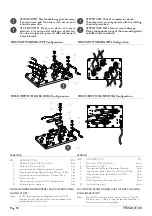
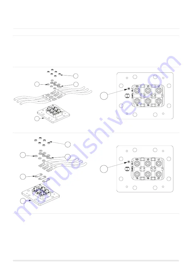
FVR PART WINDING (PW) Configuration
FVR DIRECT ON LINE (DOL) Configuration
7.1 Cavi di potenza
FVR PART WINDING (PW) Configurazione
FVR DIRETTO IN LINEA (DOL) Configurazione
The personnel, shall observe all the local safety regulations
and standards, applicable in the electrical maintenance and
installation. All the electrical connections must be carried
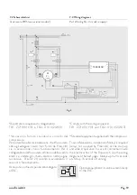
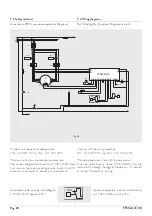
out according to the wiring diagrams (Fig. 3, 3b, 4).
Il personale deve attenersi alle normative e standard
vigenti nel luogo di installazione, riguardanti la sicurezza
elettrica della manutenzione e prima installazione. Tutte
le connessioni elettriche devo essere eseguite nel rispetto
degli schemi elettrici. (Fig. 3, 3b, 4).
1
2
5
3
6
1
2
3
4
5
6
LEGEND
REF.
DESCRIPTION Q.TY
1
Brass Nut M12 (tq 30Nm) 6 pcs
2
Brass Washer 12x24 6 pcs
3
Connection for Motor Protection Module 3 pcs
4
DOL Connection Bars 3 pcs
5
Terminal Plate 1 pcs
6
Ground Connection M6 1 pcs
DO NOT UNFASTEN OR REMOVE THE SIX NUTS LOCKING
THE INSULATING BLOCK !
LEGENDA
RIF.
DESCRIZIONE Q.TA’
1
Dado in Ottone M12 (cs 30Nm) 6 pz.
2
Rosetta in Ottone 12x24 6 pz.
3
Connessione per Modulo protezione motore 3 pz.
4
Barrette per avviamento DOL 3 pz.
5
Piastra Terminali 1 pz.
6
Connessione di terra M6 1 pz.
NON ALLENTARE O RIMUOVERE I SEI DADI CHE BLOCCANO
L’ISOLATORE !


