FTEC24_IE_00
Pag. 20
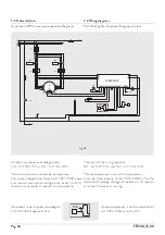
7.2 Wiring diagrams
Part Winding Start (optional Diagnose version)
7.2 Schemi elettrici
Avviamento PWS ( esecuzione opzionale Diagnose)
*Comply with the wiring sequence:
TR1 - Z(7) X(8) Y(9) and TR2 - U(1) V(2) W(3)
**Standard equipment sent with the compressor.
It can be wired directly to the T00EC45AD after the
removal of the bridge, the logic of the delays is: 10 seconds
at startup, 3 seconds at running.
*Rispettare la sequenza di collegamento:
TR1 - Z(7) X(8) Y(9) e TR2 - U(1) V(2) W(3)
**Accessorio fornito a corredo del compressore.
Può essere collegato direttamente al T00EC45AD dopo
aver rimosso il ponticello, con logica interna dei ritardi: 10
secondi in avviamento, 3 secondi in funzionamento.
Optional equipment: it can be wired directly
to T00EC45AD or to the PLC.
Accessorio a richiesta: può essere collegato
al T00EC45AD oppure al PLC.
FCS
A
B
M
3
~
W (3)
V (2)
U (1)
Y (9)
X (8)
Z (7)
TR2
*
F3
TR1
*
L1
L2
L3
N
F1
CB
HT
L1
L2
L3
T00EC45AD
N
1
L
2
14
N
L1.3
L1.1
PT1
PT2
9
8
6
5
4
3
2
1
7
10
F2
I-1/0
L1.2
11
12
FS**
3 4 5 6 7 8 9 10
11
12
X X
MR
LP1
FCS
MR
Fig.3b
T1
T2


