Fraser Anti-Static Techniques, Scotts Business Park, Bampton, Devon EX16 9DN, UK
T + 44 (0) 1398 331114 F + 44 (0) 1398 331411 E sales@fraser-antistatic.co.uk W www.fraser-antistatic.com
15
NEOS 30 OEM-DM-Iss.2
7. OPERATION & CONTROL
Signalling:
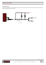
The NEOS Bars feature two open-collector outputs to enable remote monitoring of Bar status, and a logic-level DISABLE input
to allow the HV supplies to be externally disabled when not required (“Standby” mode). For example, the bar can be linked into a
machine’s safety interlock system to ensure operator safety during changeover periods.
See wiring diagram and examples below.
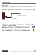
Open-collector outputs (OK, ATTENTION)
Both open-collector outputs are capable of sinking a current of up to 200 mA, allowing direct driving of external lamps or relays, or
an external LED with a suitable current limiting resistor. An internal 1k5 pull-up resistor provides a 24V signal suitable for driving a
24V PLC digital input compatible with IEC 61131-2 ‘Type 1’ or ‘Type 3’. See wiring diagram and examples in the next section.
Both output signals are active low, meaning that a signal is asserted by a connection to 0 V via a low-powered solid-state switch.
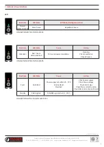
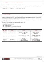
The two signals are valid 5 seconds after power is applied, according to the following conditions:
Condition
Ionisation
OK (White, Pin 2)
Attention (Black, Pin 4)
Bar powered, all OK
ACTIVE (HV ON)
ACTIVE (connected to 0 V)
ACTIVE (connected to 0 V)
Bar powered, requires
attention (e.g. cleaning)
ACTIVE (HV ON)
ACTIVE (connected to 0 V)
INACTIVE (open-circuit)
Bar not powered, overload
or hardware fault
INACTIVE (HV OFF)
INACTIVE (open-circuit)
INACTIVE (open-circuit)
Standby mode
INACTIVE (HV OFF)
INACTIVE (open-circuit)
ACTIVE (connected to 0 V)
A working Bar in good operating condition will thus internally connect both opencollector outputs to 0 V,
after a delay of up to 5 seconds after power is applied. Voltage applied to open collector outputs must not
exceed 28 V DC, and must be of the correct polarity.
The current through the open collector switch must not exceed 200 mA. Failure to limit the current into the
open collector outputs may cause permanent damage to the product. Do not connect the open collector
outputs directly to 24 V.
D
TITLE
REVISION
MATERIAL
SCALE
DRAWING No.
5
6
C
DO NOT SCALE
SHEET 1 OF 1
B
A
1
2
3
C
IF IN DOUBT - ASK
4
5
B
6
A
D
1
2
THIRD
ANGLE
3
PROJECTION
ALL SHARP EDGES AND CORNERS TO BE REMOVED
MACHINING TOLERANCES UNLESS OTHERWISE STATED
4
SPECIFICATION AND SYMBOLS TO BS308
ONE DECIMAL PLACE
TWO DECIMAL PLACES
0-100mm
100-500mm
ABOVE 500mm
SURFACE FINISHES TO BS1134
±0.1mm
±0.01mm
±0.25mm
±0.4mm
±0.75mm
A3
SCOTTS BUSINESS PARK
BAMPTON, DEVON
EX16 9DN
WWW.FRASER-ANTISTATIC.COM
TEL: 44-(0) 1398 331114
FAX: 44-(0) 1398 331411
1:5


