background image

AMA200 Rev150720

5

Controls and Indicators

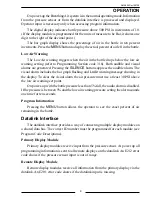
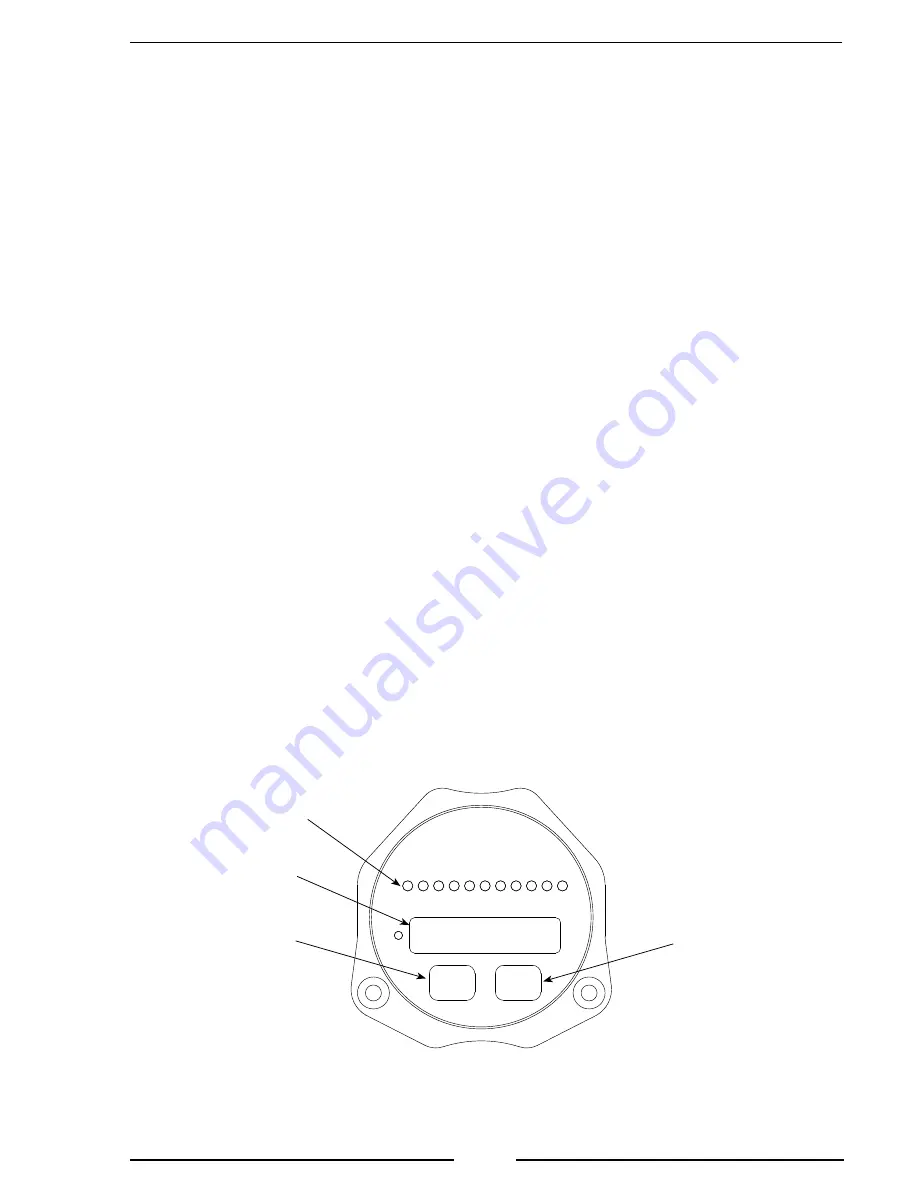
All controls and indicators are located on the front of the display module. The 

intensity of the display and LEDs are automatically adjusted for day or night operation.

LED Bar Graph

The LED bar graph display indicates the remaining percentage of air in the bottle, 

this will be proportional to the pressure sensor input. The first two LEDs indicate 5% 

and 10%, the last two LEDs indicate 90% and 95%. The other LEDs are in ten percent 

increments. All LEDs are on at full tank and flash for low air warning.

Digital Display

During normal operation this 5-digit LED display indicates tank pressure. When the 

MENU

 button is pressed it indicates the percent of air in the bottle. When the program 

access mode is selected, program specific information and settings are displayed. (Refer 

to Programming Section for more information.)

MENU

 Button

Press to show percent of air in bottle. Used when accessing program features to 

change settings or parameters.

SILENCE

 Button

Suppresses audio alarm (does not cancel the visual alarm), also used when accessing 

program features.

Figure 1.  Controls and Indicators

LED Bar 

Graph

Digital 

Display

MENU


Button

SILENCE


Button

Summary of Contents for Air Sentinel AMA200

Page 1: ...BREATHING AIR MONITORING SYSTEM MODEL AMA200 Document Number XE AMA2PM R0A FIRE RESEARCH CORPORATION www fireresearch com 26 Southern Blvd Nesconset NY 11767 TEL 631 724 8888 FAX 631 360 9727 TOLL FR...

Page 2: ...8 OPERATION 9 Datalink Interface 9 Test Mode 10 PROGRAMMING 11 Inputs 11 Program Access Mode 12 Table 1 Program Code Quick Reference 13 Program Code Descriptions 14 WIRING 16 Display Module 16 Pressu...

Page 3: ...r Warning Programmable for Different Size Air Bottles Shows Pressure and Percent of Air in the Bottle Displays Air Pressure in PSI kPa or Bar Multiple Remote Displays LED Display Brightness Automatica...

Page 4: ...controls and indicators are located on the front of the display module Refer to Controls and Indicators Pressure Sensor The pressure sensor is mounted on the air tank manifold It provides an input sig...

Page 5: ...are on at full tank and flash for low air warning Digital Display During normal operation this 5 digit LED display indicates tank pressure When the MENU button is pressed it indicates the percent of...

Page 6: ...e panel for the display and cables before cutting holes Refer to Figure 2 for layout and dimensions 2 Cut out a 2 3 4 inch diameter hole and drill four holes clearance or tapped for 10 32 mounting scr...

Page 7: ...o tighten the pressure sensor Damage to the sensor may occur 2 Tighten the sensor with a 3 4 inch wrench on the lower hex fitting 3 Connect the pressure sensor cable from the display module to the pre...

Page 8: ...the visual warning on the display The optional buzzer provided by FRC requires a cutout hole of 1 1 8 1 125 Pin 6 on the 8 pin connector at the rear of the control module is provided to connect the o...

Page 9: ...the bar graph flashing and LoAir warning message showing in the display To clear the visual alarm the air pressure must rise at least 30 PSI above the low air warning set point On power up with the bo...

Page 10: ...test mode will not activate when there is a low pressure warning 1 Press and hold the SILENCE button Result The audible alarm sounds Result The LED bar graph cycles showing empty one LED on and then...

Page 11: ...perator input every three seconds If an input is not detected within five seconds the program returns to normal operation Inputs The two pushbutton switches on the front of the display module allows t...

Page 12: ...the number increments by 1 Set the first digit to the desired number 3 Press the SILENCE button The second digit flashes Each time the SILENCE button is pressed the number increments by 1 Set the seco...

Page 13: ...and Programming E202 Invalid Program Code Entered Re Enter Code E208 Memory Failure Contact Factory E212 Pressure Sensor Voltage Out of Range Table 1 Program Code Quick Reference Notes Refer to Progr...

Page 14: ...e ID number of the primary display Code 313 Module Function Factory programmed value Pri Options Pri SLA This code sets the datalink function of the display module Two program choices are available Pr...

Page 15: ...ode has been entered Re enter program code when the digital display resets Error Code E208 Memory There is a failure with the internal memory of the module The bottle pressure shows in the display alt...

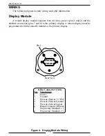
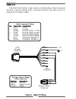
Page 16: ...link connection pins 7 and 8 to the primary display A remote display must be programmed with the same ID number as the primary display Figure 4 Display Module Wiring 8 Pin Connector Cable Pin Descript...

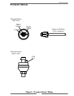
Page 17: ...AMA200 Rev150720 17 Pressure Sensor Figure 5 Pressure Sensor Wiring Signal Output Supply Voltage Ground Sensor Cable from 8 Pin Connector Pressure Sensor Side View Pressure Sensor Top View Vent Port...

Page 18: ...ND RED BLK ORG WHT GRN YEL BLU BRN 8 Pin Deutsch Connector 8 Pin Connector Wiring Pin Wire Color Description 1 Red Power 2 Black Ground 3 Orange Pressure Sensor 5 VDC 4 White Pressure Sensor Ground 5...

Page 19: ...AMA200 Rev150720 19 NOTES...

Page 20: ...AMA200 Rev150720 20...

Reviews: