background image

p. 11

AVM Around Vehicle Monitoring System Installation Guide


inView 360 HD Installation Guide

© Safe Fleet | July 2020 | All rights reserved 

Document Number: XE-SNB100-C00-INSTALLPM-R0A

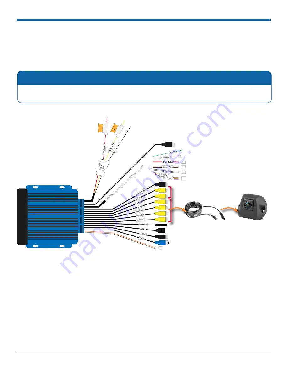
Connecting Cameras to the ECU

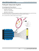
The cameras are labeled to indicate where they should be mounted on the vehicle - FRONT, RIGHT, LEFT, REAR� When 

connecting cameras to the ECU, it is important that you do the following: 

•  Connect the labeled camera to the correct corresponding camera interface on the ECU harness� 

•  Connect each camera to an extension cable before connecting it to the ECU� 

Connect the cameras as indicated in the following diagram� 

For Cameras 5 & 6� Not 

used� during calibration� 

4 x Camera  

Extension Cables

4 x Camera Units

Conn

e

ct

t

o

Conn

e

ct

t

o

 NOTE: Spacing the Calibration Pads

The inView 360 HD AVM system comes with two extra camera ports for cameras 5 and 6� Cameras connected to 

ports 5 and 6 are not required for the calibration procedure� 

 NOTE: Extra Camera Ports

Summary of Contents for InView 360 HD AVM

Page 1: ...Safe Fleet All rights reserved Document Number XE SNB100 C00 INSTALLPM R0A Safe Fleet July 2020 All rights reserved Installation Guide Around Vehicle Monitoring System AVM...

Page 2: ...ations for Long Nosed Vehicles 8 Camera Placement Considerations for Specially Shaped Vehicles 9 Putting the Components Together 10 Connecting to the Power Source 10 Connecting Cameras to the ECU 11 C...

Page 3: ...edestrians and vehicles How Does the inView 360 HD AVM Work High definition cameras are placed high up on the front rear left and right sides of the vehicle Videos from these four cameras are sent to...

Page 4: ...ble Extensions of different lengths 8 m for the front camera 12 m for the left and right vehicle side cameras 15 m for the back camera Extra cable extensions can be ordered separately 1 x Y Splitter 1...

Page 5: ...XE SNB100 C00 INSTALLPM R0A 1 x Cable Harness 1 x ECU w Lock Removable Front Cover 4 x Camera Cable Extensions In 3 different lengths 8m front 12m left right 15m back Extra cable extensions can be or...

Page 6: ...M R0A 4 x Camera Modules 2 9 MP 4 x Camera Housings 1 x Y Splitter 1 x External GPS Antenna 1 x Ethernet Adapter 1 x External Wi Fi Antenna 1 x Dashboard Push Button Mount Template 3 x Push Buttons 1...

Page 7: ...ystem calibration Routing Power Signals and Buttons After you have selected an optimal location for the ECU and mounted it you can begin routing the power and signal cables as well as the push buttons...

Page 8: ...a Placement Considerations When considering where to mount the cameras it is important to follow these general guidelines Place the cameras as high and as centered as possible to ensure that there are...

Page 9: ...up and in the center might not be an option The added equipment might block a camera s field of view This is a situation where you should consider mounting the camera slightly off center Vehicle Cente...

Page 10: ...ng to the power sources please ensure the following Red goes to vehicle power Yellow goes to vehicle ignition Black goes to vehicle ground You will have to splice fuses onto the red vehicle power and...

Page 11: ...the following Connect the labeled camera to the correct corresponding camera interface on the ECU harness Connect each camera to an extension cable before connecting it to the ECU Connect the cameras...

Page 12: ...monitor directly to the ECU harness CVBS cable or to the VGA cable VGA HD monitor Choose the connection method for the type of monitor that will be used To connect to a standard monitor use the CVBS c...

Page 13: ...ution monitor Primary monitor Example monitor shown CVBS Additional hardware required for connecting to a Safe Fleet recorder or additional monitor Y Splitter OR Safe Fleet Recorder Second standard mo...

Page 14: ...your monitor is an HD monitor then you can connect it to the ECU via the VGA connector In this scenario the system can be configured to turn off video to the HD monitor for safety and because the rec...

Page 15: ...Using a combination of the VGA and CVBS video lines you can connect up to three devices of the following combinations 1 x HD monitor 1 x standard resolution monitor and 1 x recorder 1 x HD monitor an...

Page 16: ...ton The driver presses this button to cycle through the different camera views for the vehicle front rear left top Red Event Button The driver presses this button when an event vehicle collision safet...

Page 17: ...tton Mount Template Dashboard Push Button Mount Template Event Button Cable Harness Black Push Button Switch Green Push Button Switch Red Push Button Switch 3 Install the dashboard push button mount t...

Page 18: ...turn signals are connected to the ECU harness Left Right Reverse Trigger connector through the View Select Signal Cable Harness then the driver will receive with a left right rear view when the driver...

Page 19: ...ation and documentation related to the inView 360 HD system please visit the inView 360 HD product page on the FRC website http www fireresearch com This product page can be found under the Video top...

Reviews: