PRO-S Rev1104
13
Installation
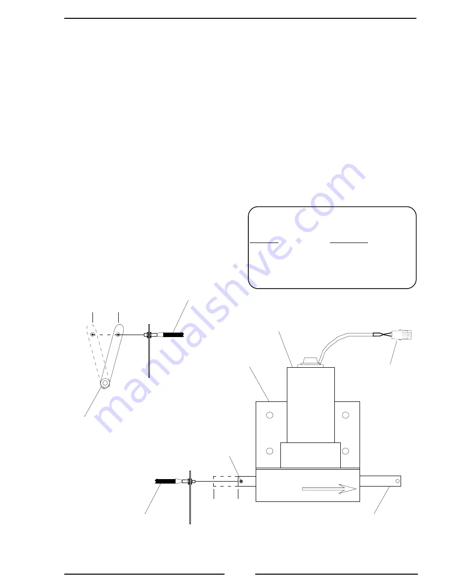
1. Place the throttle servomotor in position and secure.
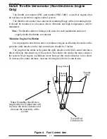
Note: The total motion of the linear actuator rod is approximately 1.85
inches. The motion of the fuel control arm must be more than 1.85 inches
to prevent damage to the arm. It is recommended that the fuel control arm
have a two inch stroke at the point the cable attaches.
2. Connect the throttle cable to the linear actuator rod and the fuel control arm.
3. Test the motion of the fuel control arm by operating the servomotor linear
actuator rod to its minimum and maximum positions. Ensure that the fuel control
arm operates freely. (C12 VDC to red wire and ground to black wire
to extend actuator rod, reverse wires to retract rod.)
4. Connect the 2-pin connector to the servomotor cable. (Refer to Wiring section.)
Figure 5. Throttle Servo Motor
Typical
Fuel
Control
Arm
Set
Screw
INCREASE
Throttle
Cable
1.85"
Throw
MAX
MIN
Throttle
Servo
Motor
Linear
Actuator
Rod
Mounting
Flange
Throttle
Cable
2"
Stroke
MIN
MAX
Typical
Throttle Cable
and Support
Bracket
Throttle Servo Motor Cable
Connector
Pin/Wire
Description
A/Red
+12 VDC to Extend
B/Black
+12 VDC to Retract
Note: Extend refers to the INCREASE
direction as shown on the servo motor.
2-Pin
Packard
Connector
Note: The throttle cable is not
supplied with the throttle servomotor.


