PRO-S Rev1104
27
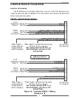
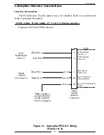
Figure 10. Cummins PRO-S 1 Wiring
(Sheet 2 of 3)
Cummins Harness Connections
Interface Information
The ECM Remote Acceleration Option has to be set to ON. The diagnostic tool
cannot be used to do this, an Insight service tool must be used. Refer to an authorized
dealer to program this option.
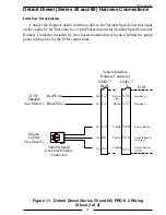
ISB, ISC, and ISL Engine Interface
ECM 50-Pin
B Connector
J1587 (–)
J1587
Datalink (See
Sheet 1)
Black Wire
Red Wire
J1587 (+)
50
49
20
10
9
45
6
REMOTE THROTTLE RETURN (SRTN B)
Engine
Control
(See Sheet 1)
REMOTE THROTTLE PEDAL POSITION INPUT
REMOTE TH5VDC (VSENSOR B)
Red Wire
Black Wire
White Wire
SELECTED THROTTLE CONTROL SWITCH
REMOTE THROTTLE ON/OFF INPUT
Note: Supply a
ground when the
pump interlock
circuit is engaged.
Note: Supply a ground fwhen the pump
interlock circuit is engaged.
This assumes that the ECM is set
with Automotive governor as the
default mode.
ECM 50-Pin
J2 Connector
J1587 Datalink (–)
J1587
Datalink (See
Sheet 1)
Black Wire
Red Wire
J1587 Datalink (+)
20
10
32
21
26
03
14
ECM Return (Sensor)
Engine
Control
(See Sheet 1)
Remote Accelerator Position
Sensor Supply
Red Wire
Black Wire
White Wire
Max Operating Speed/Governor Type Switch
Remote Accelerator On/Off Switch
Note: Supply a
ground when the
pump interlock
circuit is engaged.
Note: Supply a ground when the pump
interlock circuit is engaged.
This assumes that the ECM is set
with Automotive governor as the
default mode.
ISB02/ISC03/ISL03
CM850 Model Engines


