background image

PRO-S Rev1104

43

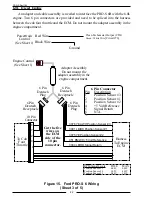
Note: Two 6 pin Deutsch connectors are provided and need to be spliced into
the harness between the cab foot throttle 10 pin connector and the ECM

Ford Adapter and Cable Detail (6.0 L Engines)

Note: Do not mount the adapter assembly in the engine compartment.

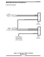
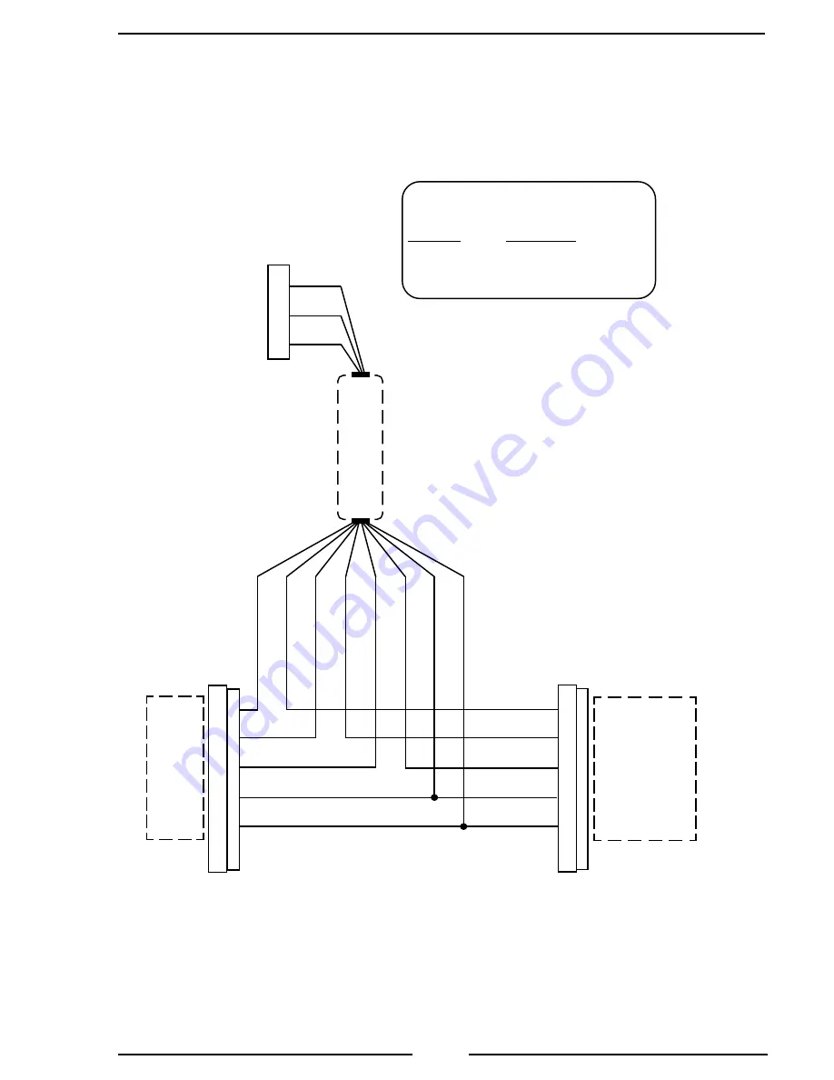
Figure 15.  Ford PRO-S 6 Wiring

(Sheet 4 of 5)

6.0L Adapter Assembly

Connector

Pin/Wire

Description

A/Black

Ground

B/White

+12 V Interlock

C/Red

Signal To Engine ECM

Wires To

10 Pin

Connector

Wires To

Engine ECM

Harness

Note: An adapter and cable assembly
replaces the basic PRO-S cable when
connecting the PRO-S 6B to Ford
6.0L engines.

3076 YEL/WH

3091 LB/BK

3075 YE

351 BN/WH

3094 LB/RD

1

2

3

4

5

6

WHT

BLK

RED

BLU

GRN

BRN

ORG

YEL

Adapter

Assembly

1

2

3

4

5

6

1

2

3

4

5

6

1

2

3

4

5

6

Pin 8

Pin 7

Pin 2

Pin 4

Pin 10

BLK

WHT

RED

A

B

C

3 Pin

Packard

Plug

Summary of Contents for PRO-S 1

Page 1: ...PRO S Rev1104 1 FIRE RESEARCH CORPORATION http www fireresearch com 26 Southern Blvd Nesconset NY11767 TEL 631 724 8888 FAX 631 360 9727 TOLL FREE 1 800 645 0074 PRESSURE GOVERNOR ...

Page 2: ... 17 System Options 18 CALIBRATION 19 RPM Calibration PRO S 3 6 and 8 19 High Idle Option Calibration 20 3rd Gear Lock up RPM Calibration Ford 6 0L 20 DIAGNOSTICS 21 WIRING 22 Power 22 High Idle 23 Pressure Transducer 24 Common OME Connectors 25 Cummins PRO S 1 Cables 26 Cummins Harness Connections 27 Detroit Diesel Series 50 and 60 PRO S 2 Cables 30 Detroit Diesel Series 50 and 60 Harness Connecti...

Page 3: ...6 Figure 11 Detroit Diesel Series 50 and 60 PRO S 2 Wiring 30 Figure 12 Non Electronic PRO S 3 Wiring 32 Figure 13 Navistar and Detroit Diesel Series 40 PRO S 4 Wiring 34 Figure 14 Caterpillar PRO S 5 Wiring 36 Figure 15 Ford PRO S 6 Wiring 40 Figure 16 Mack PRO S 7 Wiring 46 Figure 17 Scania PRO S 8 Wiring 48 Figure 18 Mercedes PRO S 10 Wiring 50 Figure 19 Flyback Diode Wiring 52 Ford PRO S 6 Cab...

Page 4: ...ant engine RPM The pump discharge pressure is monitored it can vary but will be limited to an increase of 30 PSI If the discharge pressure increases 30 PSI the pressure governor will automatically lower the engine RPM to reduce the discharge pressure All controls and indicators are located on the front of the control module Features Power Up in Pressure Mode Automatic Regulation of Pump Discharge ...

Page 5: ...mmins IS Series Detroit Diesel Series 50 and 60 Non Electronic Navistar and Detroit Diesel Series 40 Caterpillar Ford Mack Scania Mercedes SUPPLY VOLTAGE See Note 1 12 VDC 12 VDC 12 VDC 12 VDC 12 VDC 12 VDC 12 VDC 12 VDC 12 VDC SUPPLY CURRENT 1 0 AMP 1 0 AMP 3 0 AMP 1 0 AMP 1 0 AMP 1 0 AMP 1 0 AMP 1 0 AMP 1 0 AMP RESPONSE Idle to full governed speed 5 SEC 5 SEC 30 SEC 5 SEC 5 SEC 5 SEC 5 SEC 5 SEC...

Page 6: ...utput Voltage PRESSURE PSI VOLTAGE VDC 0 0 5 100 1 917 150 2 625 200 3 33 250 4 04 300 4 75 Pressure Transducer Model Number PRO31PT2 Pressure Range 0 300 PSI Proof Pressure 800 PSI Excitation Voltage 5 VDC Output Voltage 0 5 4 75 VDC See Table 2 ...

Page 7: ... by 4 25 inches wide by 3 5 inches deep 4 5 inches deep on non electronic and 24 VDC units All controls and indicators are located on the front of the control module Refer to Controls and Indicators Pressure Transducer The pressure transducer is mounted on the pump discharge manifold It provides an input signal to the control module that is proportional to the discharge pressure Throttle Servomoto...

Page 8: ...agnostic error code IdLE for engine idle the pressure setting or the RPM setting The LED digital display has daylight bright digits at least 0 56 inch high INCREASE Button During operations the yellow INCREASE button raises pressure or RPM setting This button is also used in the programming of the pressure or RPM preset values DECREASE Button During operations the yellow DECREASE button lowers pre...

Page 9: ...PRO S Rev1104 9 Figure 1 Controls and Indicators PRESSURE Button DECREASE Button IDLE Button PRESET Button INCREASE Button SETTING Display RPM Button PRESSURE LED RPM LED ...

Page 10: ...e 2 for layout and dimensions 2 Cut out a 3 75 inch diameter hole and drill four holes for mounting screws 3 Place control module in position and secure with four screws 10 32 mounting hardware is recommended Note If the optional remote high idle kit is not being installed ensure that the high idle cap and pin B to pin C jumper wire is installed on the end of the control module high idle cable 4 C...

Page 11: ... hole Caution Do not use the main body that houses the electronics to tighten the pressure transducer Damage to the transducer may occur 2 Tighten the transducer with a 9 16 inch wrench on the lower hex fitting 3 Connect the pressure transducer cable from the control module to the pressure transducer Refer to Wiring section Figure 3 Pressure Transducer Caution Do not use the main body that houses ...

Page 12: ... Engine Oscillation It is important to note that in order to minimize engine oscillations the stroke at the point the cable attaches to the fuel control arm should be 2 inches The length of the stroke at the point the cable attaches to the fuel control arm has a direct effect on the sensitivity of the system The shorter the stroke the more sensitive the system Most engine oscillations occur becaus...

Page 13: ... positions Ensure that the fuel control arm operates freely Connect 12 VDC to red wire and ground to black wire to extend actuator rod reverse wires to retract rod 4 Connect the 2 pin connector to the servomotor cable Refer to Wiring section Figure 5 Throttle Servo Motor Typical Fuel Control Arm Set Screw INCREASE Throttle Cable 1 85 Throw MAX MIN Throttle Servo Motor Linear Actuator Rod Mounting ...

Page 14: ...stalled on the end of the control module high idle 3 pin Deutsch connector This cap is removed to install the high idle cable Note Refer to the high idle calibration procedure after the installation is complete to adjust the 2500 ohm potentiometer for high idle engine RPM Install the potentiometer in a location that will allow access to adjust it during the calibration procedure For wiring of the ...

Page 15: ...ess either button momentarily to change the RPM setting by 10 RPM Press and hold the button for more than 2 seconds and the RPM setting will change by 50 RPM twice and then by 100 RPM until the button is released Switching Between Operating Modes No variation in discharge pressure or RPM will occur when changing between pressure and RPM modes When changing to RPM mode the RPM setting will be the R...

Page 16: ...n empty water tank a problem on the intake line or when switching the water supply source In pressure mode the PRO S will increase the engine RPM and attempt to maintain the selected pressure setting If the discharge pressure drops below 45 PSI but stays above 15 PSI the PRO S will go into a low water cycle It will set the engine to 1100 RPM if the pressure does not rise above 45 PSI in 7 seconds ...

Page 17: ...REASE button to select the operating RPM 3 Press IDLE button to bring engine to idle RPM Result SETTING display shows IdLE Change Preset Setting Pressure or RPM The preset button allows the operator to go to a pre programmed pump pressure or engine RPM during operations The setting will be shown on the SETTING display This procedure is to change the setting in the program Note The engine must be r...

Page 18: ...d To engage the high idle place the high idle switch to ON The high idle indicator light will go on and the engine will run at the set RPM The PRO S SETTING display will show the high idle RPM With the high idle switch set to on the PRO S controls will operate normally for RPMs above the high idle RPM The DECREASE and IDLE buttons will not lower the engine RPM below the high idle setting It is rec...

Page 19: ...RPM LED indicator goes on 2 Press IDLE button two times Result SETTING display shows CAL flashing Note Confirmation of selecting the calibration mode has to be input within five seconds of CAL flashing in the SETTING display 3 Press IDLE button two times again to confirm selection of calibration mode Result SETTING display shows CAL steady 4 Press PRESET button Result SETTING display alternately f...

Page 20: ...k up RPM Calibration Ford 6 0L The 3rd gear lock up is factory set at 1200 RPM This procedure is to change the setting in the program Note The engine must be running and the pump engaged interlock circuit must be closed 1 Press IDLE button Result SETTING display shows IdLE 2 Press RPM mode button to select RPM mode Result RPM LED indicator goes on Note The RPM display must show IdLE 3 Press and ho...

Page 21: ...t running ignition key on Non Electronic engines RPM signal not detected Broken wire bad connector contact on alternator cable No voltage at the interlock input Internal datalink problem bad control module Datalink shorted Transducer cable not connected Broken wire bad connector contact on transducer cable Defective pressure transducer E6 N A N A Low supply water intake line problem valve closed p...

Page 22: ... becomes operational The interlock circuit may include relays switches and or indicator lights for the following conditions Parking Brake On PTO Engaged Transmission In Drive Neutral High Idle OK To Pump Throttle Ready From Control Module Power Supply 3 Pin Deutsch Connector Power Supply Cable White Ignition Key From Interlock Circuit 12 VDC Power Supply Cable Connector Pin Wire Description A Red ...

Page 23: ...12VDC From Pump Engaged 12VDC To Control Module White Interlock Wire Located in power cable Pump Engaged Indicator Light GND NC NO NC NO NO C C GND GND GND High Idle Cable High Idle Cable Connector Pin Wire Description A Red 5 VDC B Black Ground C White Signal Note If the optional remote high idle kit is being installed the high idle cap must be removed It is installed on the end of the control mo...

Page 24: ...n Deutsch Connector Pressure Transducer Cable Pressure Transducer Pressure Transducer Cable 3 Pin Sensor Connector Pin Wire Description A Black Ground B Red SupplyVoltage C White SignalOutput Pressure Transducer Cable 4 Pin Deutsch Connector Pin Wire Description 1 Red SupplyVoltage 2 Black Ground 3 White SignalOutput 4 Yellow CableShield Pressure Transducer ...

Page 25: ...onnectors Common OME Connectors Typical 6 pin Deutsch diagnostic connector PinAJ1587 Datalink Positive Pin B J1587 Datalink Negative Typical 9 pin Deutsch diagnostic connector Pin F J1587 Datalink Positive Pin G J1587 Datalink Negative FRONT VIEW B F E A C D G H J E D A B C F FRONT VIEW ...

Page 26: ...PM Sig J1587 GOVERNOR High Idle Pressure Sensor A C B B Power Supply Refer to Figure 6 Engine Control See Sheet 2 E Connector Key A 4 Pin Deutsch B 3 Pin Deutsch C 3 Pin Packard D 2 Pin Packard E 3 Pin Sensor Engine Control Cable Connector Pin Wire Description A Black SignalReturn B White SignaltoECM C Red 5 VDC Reference RPM Sig J1587 J1587 Datalink See Sheet 2 D J1587 Datalink Cable Connector Pi...

Page 27: ...LE CONTROL SWITCH REMOTE THROTTLE ON OFF INPUT Note Supply a ground when the pump interlock circuit is engaged Note Supply a ground fwhen the pump interlock circuit is engaged This assumes that the ECM is set with Automotive governor as the default mode ECM 50 Pin J2 Connector J1587 Datalink J1587 Datalink See Sheet 1 Black Wire Red Wire J1587 Datalink 20 10 32 21 26 03 14 ECM Return Sensor Engine...

Page 28: ...at the ECM is set with Automotive governor as the default mode Note Supply a ground when the pump interlock circuit is engaged ECM 50 Pin J2 Connector J1587 Datalink J1587 Datalink See Sheet 1 Black Wire Red Wire J1587 Datalink 20 10 32 21 26 03 14 ECM Return Sensor Engine Control See Sheet 1 Remote Accelerator Position Sensor Supply Red Wire Black Wire White Wire Max Operating Speed Governor Type...

Page 29: ...PRO S Rev1104 29 This page intentionally left blank ...

Page 30: ... Engine Control See Sheet 2 E C Connector Key A 4 Pin Deutsch B 3 Pin Deutsch C 3 Pin Packard D 2 Pin Packard E 3 Pin Sensor Pressure Transducer Refer to Figure 8 High Idle Cap Refer to Figure 7 Engine Control Cable Connectors Pin Wire Description A Black VehicleSensorReturn B White Signal C Red VehicleHarness5Volt RPM Sig J1587 J1587 Datalink See Sheet 2 D J1587 Datalink Cable Connector Pin Wire ...

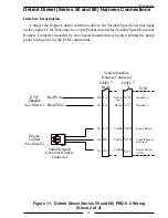
Page 31: ...facturer located behind the pump panel to plug into for the ECM connections Figure 11 Detroit Diesel Series 50 and 60 PRO S 2 Wiring Sheet 2 of 2 Vehicle Interface Harness Connector ECM Engine Control See Sheet 1 Variable Speed Governor Harness Connector J1587 Datalink See Sheet 1 Red Wire Black Wire C 3 D 1 A 3 C 2 C 1 952 510 916 900 901 Sensor Return Variable Speed Governor Sensor Supply 5VDC D...

Page 32: ...re 6 E C D Throttle Servo Motor Refer to Figure 5 Alternator See Sheet 2 Connector Key A 4 Pin Deutsch B 3 Pin Deutsch C 2 Pin Deutsch D 2 Pin Packard E 3 Pin Sensor Alternator Cable Connector Pin Wire Description 1 Red Terminal 2 Black Ground High Idle Cap Refer to Figure 7 Pressure Transducer Refer to Figure 8 Note Extend refers to the INCREASE direction as shown on the servo motor Throttle Serv...

Page 33: ...small positive terminal on the alternator Some names used for this terminal Alternator Tap Stator Tap A C Tap Tachometer Signal Connection Tach Output Tach Terminal Do not connect the red wire to the large battery BAT terminal Connect the black wire to chassis ground Figure 12 Non Electronic PRO S 3 Wiring Sheet 2 of 2 ...

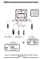
Page 34: ...e RPM Sig J1587 GOVERNOR High Idle Pressure Sensor RPM Sig J1587 A C B B Power Supply Refer to Figure 6 Engine Control See Sheet 2 E J1587 Datalink See Sheet 2 D Connector Key A 4 Pin Deutsch B 3 Pin Deutsch C 3 Pin Packard D 2 Pin Packard E 3 Pin Sensor J1587 Datalink Cable Connector Pin Wire Description A Red Datalink B Black Datalink Engine Control Cable Connector Pin Wire Description A Black R...

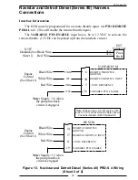
Page 35: ...onnector ATA J1587 Datalink See Sheet 1 Black Wire Red Wire PinA ATA Pin B REMOTE THROTTLE INPUT RESCM VARIABLE PTO ENABLE 5VDC REFERENCE REMOTE THROTTLE GROUND 11 19 14 17 Engine Control See Sheet 1 White Wire Black Wire Red Wire Note Supply 12 when the pump interlock circuit is engaged Note 2004 and newer model engines with code 12VXY and the Remote Engine Speed Controller Module RESCM installed...

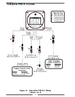
Page 36: ...r Throttle RPM Sig J1587 GOVERNOR High Idle Pressure Sensor RPM Sig J1587 A C B B Power Supply Refer to Figure 6 Engine Control See Sheets 2 4 E J1587 Datalink See Sheets 2 4 D Connector Key A 4 Pin Deutsch B 3 Pin Deutsch C 2 Pin Deutsch D 2 Pin Packard E 3 Pin Sensor Engine Control Cable Connector Pin Wire Description 1 White ThrottlePMW 2 BlackSensorCommon J1587 Datalink Cable Connector Pin Wir...

Page 37: ...s with 70 pin OEM connector Figure 14 Caterpillar PRO S 5 Wiring Sheet 2 of 4 J1587 Datalink See Sheet 1 Engine Control See Sheet 1 J1587 Datalink Negative J1587 Datalink Positive Black Wire White Wire K999 GN 993 BR G845 PU Input Sensor Common 2 Input 1 PTO ON OFF Switch Input 8 Remote Throttle PWM ECM Black Wire Red Wire 70 Pin Vehicle Harness Connector Note Supply a ground when the pump interlo...

Page 38: ...Engine Control See Sheet 1 J1587 Datalink Negative J1587 Datalink Positive Black Wire White Wire K999 GN L901 GY K982 YL Multi Function Sensor Common Multi Function Input 1 PTO ON OFF Switch Multi Function Input 3 Remote Throttle PWM 30 31 8 ECM 1 7 Black Wire Red Wire 40 Pin Vehicle Harness Connector Note Supply a ground when the pump interlock circuit is engaged ...

Page 39: ...interlock circuit Refer to the wire diagram below Figure 14 Caterpillar PRO S 5 Wiring Sheet 4 of 4 J1587 Datalink See Sheet 1 Engine Control See Sheet 1 J1587 Datalink Negative Note Supply 12 VDC when the pump interlock circuit is engaged J1587 Datalink Positive White Wire Black Wire C993 BR C985 BU C986 BR 8 VDC Sensor Common Ground Throttle Position Input PWM 35 37 29 ECM 1 7 Black Wire Red Wir...

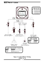
Page 40: ...t Throttle C Red SignalToEngineECM Power Supply Engine Control High Idle Cap Refer to Figure 7 Power Supply Engine Control High Idle Pressure Sensor Throttle RPM Sig J1587 GOVERNOR High Idle Pressure Sensor RPM Sig J1587 C B B Power Supply Refer to Figure 6 Powertrain Control See Sheet 2 or 3 Connector Key A 4 Pin Deutsch B 3 Pin Deutsch C 2 Pin Deutsch D 3 Pin Packard E 3 Pin Sensor RPM Signal Co...

Page 41: ...t will rise to 12 VDC Engine Control Signal will be 0 6 volts at idle and rise to approximately 3 1 volts as the foot pedal is pressed Engine Control See Sheet 1 Cab Foot Throttle Black Wire White Wire IdleValidation Engine Control Signal 0 6 to 3 1 volts Red Wire To Engine ECM Cab Foot Throttle Connector Note Use a plug and receptacle on the Engine Control Signal wire so the ends can be reconnect...

Page 42: ...he five wires on the ECM side of the 10 pin connector To Cab Foot Throttle Harness To Engine ECM 6 Pin Deutsch Plug 6 Pin Deutsch Receptacle 8 7 2 4 10 3076 YEL WH Position Sensor 3 3091 LB BK Position Sensor 1 3075 YE Position Sensor 2 351 BN WH 5 Volt Reference 3094 LB RD Signal Return 6 Pin Deutsch Receptacle 6 Pin Deutsch Plug Adapter Assembly Do not mount the adapter assembly in the engine co...

Page 43: ... 4 of 5 6 0L Adapter Assembly Connector Pin Wire Description A Black Ground B White 12 V Interlock C Red SignalToEngineECM Wires To 10 Pin Connector Wires To Engine ECM Harness Note An adapter and cable assembly replaces the basic PRO S cable when connecting the PRO S 6B to Ford 6 0L engines 3076 YEL WH 3091 LB BK 3075 YE 351 BN WH 3094 LB RD 1 2 3 4 5 6 WHT BLK RED BLU GRN BRN ORG YEL Adapter Ass...

Page 44: ...S 6 Wiring Sheet 5 of 5 To Engine Control See Sheet 1 GreenwirewillgolowwhentheengineRPM goes above the program third gear lock up setting Factory set to 1200 RPM To Adapter Assembly See Sheet 3 FRC Torque Lock up Module Black Wire Red Wire 12 VDC GND White Wire Blue Wire Green Wire Brown Orange Wire To PCM Pin 14 Locate the Brown Orange Trace wire Circuit 12A650 in the harness bundle that passes ...

Page 45: ...PRO S Rev1104 45 This page intentionally left blank ...

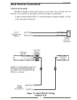
Page 46: ... Pressure Sensor Throttle RPM Sig J1587 GOVERNOR High Idle Pressure Sensor C B B Engine Control See Sheet 2 E Connector Key A 4 Pin Deutsch B 3 Pin Deutsch C 3 Pin Packard D 2 Pin Packard E 3 Pin Sensor J1587 Datalink See Sheet 2 D J1587 Datalink Cable Connector Pin Wire Description A Red Datalink B Black Datalink Engine Control Cable Connector Pin Wire Description A Black Signal From Cab Foot Thr...

Page 47: ...ignal will be 0 7 volts at idle and rise to approximately 3 8 volts as the foot pedal is pressed J1587 Datalink See Sheet 1 J1587 Negative B Black Wire Red Wire J1587 Positive A Vehicle ECU J3 Connector 14 15 Cab Foot Throttle Engine Control Signal 0 7 to 3 8 volts To Engine ECM Cab Foot Throttle Connector Engine Control See Sheet 1 Black Wire Red Wire Note Use a plug and receptacle on the Engine ...

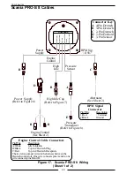
Page 48: ...r Supply Refer to Figure 6 Engine Control See Sheet 2 E Alternator See Sheet 2 D Connector Key A 4 Pin Deutsch B 3 Pin Deutsch C 2 Pin Deutsch D 3 Pin Packard E 3 Pin Sensor RPM Signal Connector Pin Wire Description 1 Red Terminal 2 Black Ground B B Engine Control Cable Connectors Pin Wire Description A White IdleValidation B Black To pin C Deutsch Plug C Red To pin C Deutsch Recepticle There are ...

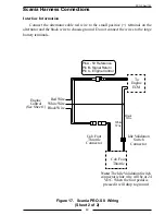
Page 49: ...ssis ground Do not connect the wires to the large battery terminals To Engine ECM Idle Validation Switch Connector Cab Foot Throttle Cab Foot Throttle Connector Engine Control See Sheet 1 White Wire Black Wire Red Wire White Wire Note The Idle Validation Switch connector white wire will be at 24 VDC When the foot pedal is pressed it will drop to ground Black Wire Pin A 5V Reference Pin B Signal Re...

Page 50: ... RPM Sig J1587 GOVERNOR High Idle Pressure Sensor A C B B Power Supply Refer to Figure 6 Engine Control See Sheet 2 E Connector Key A 4 Pin Deutsch B 3 Pin Deutsch C 3 Pin Packard D 2 Pin Packard E 3 Pin Sensor Engine Control Cable Connector Pin Wire Description A Black SignalReturn B White SignaltoECM C Red 5 VDC Reference RPM Sig J1587 J1587 Datalink See Sheet 2 D J1587 Datalink Cable Connector ...

Page 51: ...4 J1587 Datalink See Sheet 1 Sensor Ground Throttle Pedal Remote Black Wire Red Wire Black Wire J1587 VCU 21 Pin Connector VCU 18 Pin Connector 17 18 7 Engine Control See Sheet 1 Remote Throttle SignalAnalog Remote PTO Power Supply Throttle Select Red Wire White Wire Note Supply a ground when the pump interlock circuit is engaged ...

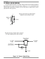
Page 52: ...etc It is recommended that a flyback diode be installed on inductive devices that share a common power source ground with a FRC governor Typical circuit showing a flyback diode installed across an inductive load Diode Inductive Load Diagram showing a flyback diode connected on a typical pump primer motor solenoid GND V Primer Motor Solenoid 12 VDC Supply From Primer Motor Switch To Primer Motor Gr...

Reviews: