PRO-S Rev1104
10
INSTALLATION
Install Control Module
Note: The control module can be mounted anywhere on the pump panel. It
should be mounted close to the engine warning indicators.
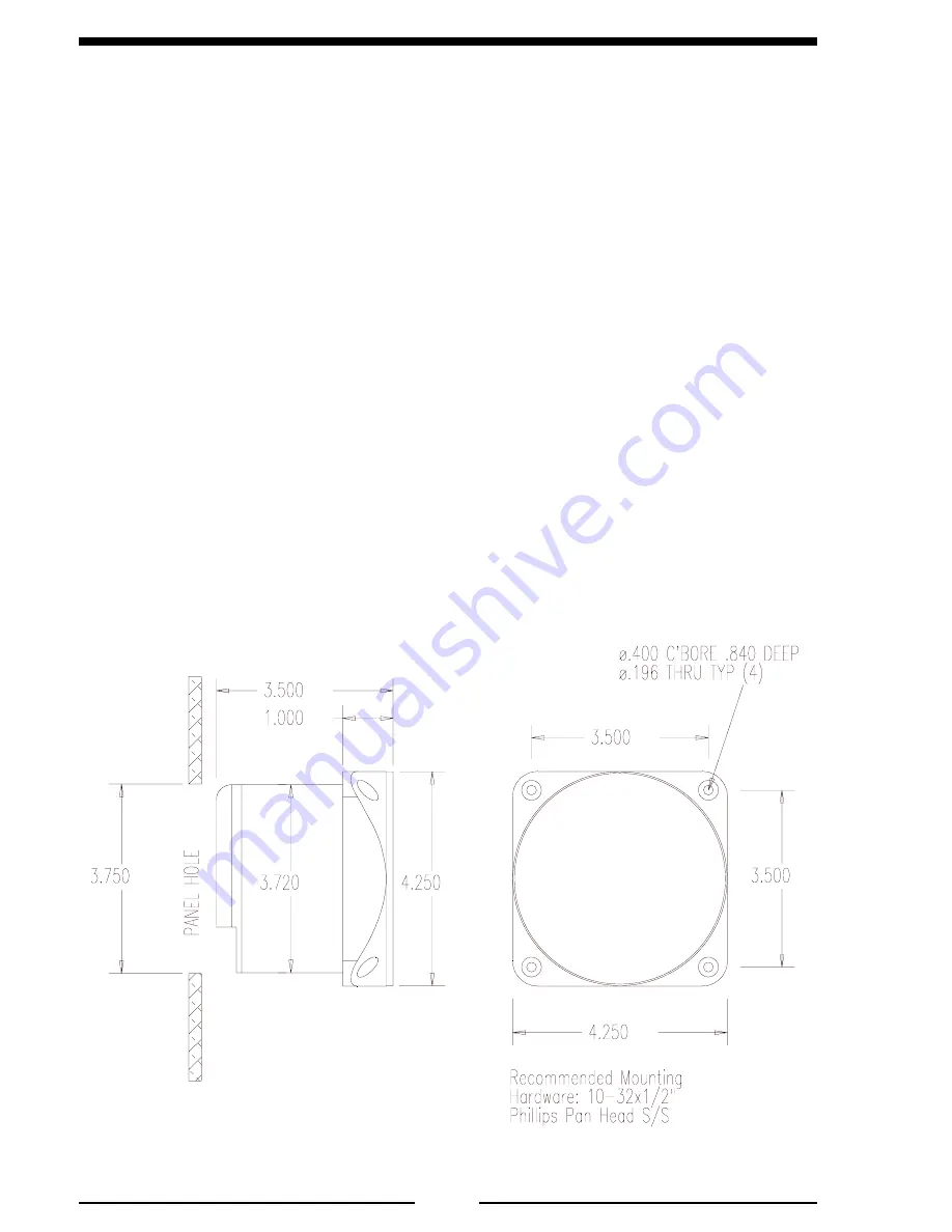
1. Measure and mark mounting location for control module panel cutout and
mounting screw holes. Make sure there is clearance behind the panel for the
module and cables before cutting holes. Refer to Figure 2 for layout and
dimensions.
2. Cut out a 3.75-inch diameter hole and drill four holes for mounting screws.
3. Place control module in position and secure with four screws (10-32 mounting
hardware is recommended).
Note: If the optional remote high idle kit is not being installed, ensure that the
high idle cap (and pin B to pin C jumper wire) is installed on the end of the
control module high idle cable.
4. Connect cables at rear of the contol module. (Refer to Wiring section.)
Figure 2. Control Module Mounting Dimensions
Note: Non-electronic and 24 VDC
units are 4.500".
Measurements are in inches.


