TH4C Installation Guide
p. 39
TH4C Advanced Configuration
© Safe Fleet | May 2019 | All rights reserved
Document Number: XE-SNB2-TH4CPM-R0A
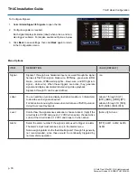
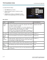
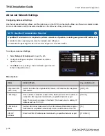
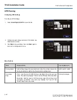
iVML Subnet
Mask
Set the subnet mask for the iVML IP Address as determined by a qualified
network expert. Use a value between 0 and 32.
[24]
Default
Gateway
Enter the Default Gateway IP address for communicating with the cellular
modem, as determined by a qualified network expert.
[172.30.2.1]
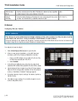
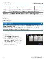
G-Sensor
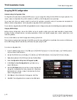
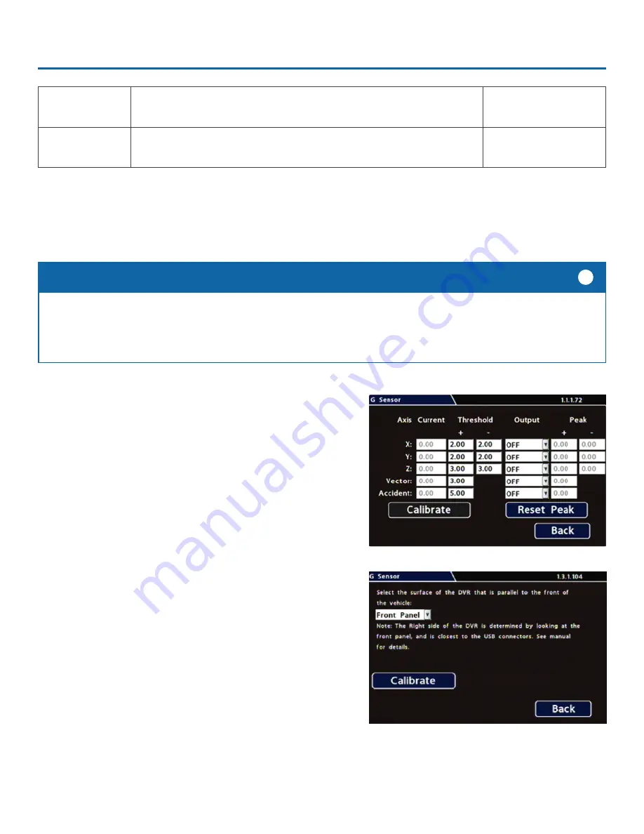
Configuring G-Sensor Options
i. Ensure all DVR surfaces are parallel to the front of the
vehicle and perpendicular to the floor.
ii. Click
Calibrate
.
3.
In the G Sensor calibration menu, from the drop down field,
select the DVR surface that is parallel to the front of the vehicle.
4. Click Calibrate for the G Sensor to set the X/Y/Z axis planes,
based on the mounting surface selection. When the process
is done, a "Calibration Complete" message appears.
5. If required, adjust G Sensor settings. For details, see Menu
Options, below.
6. Click Back to save settings, then click Back again to return
to the Configuration menu.
To configure G-Sensor settings:
1. Select
Alarm/Signal
G-Sensor
to open the tab.
2. If this is a new system installation, or the DVR has been
relocated, perform the following Calibration procedure:
The G-Sensor must be calibrated when initially installed or if the unit is relocated, and the procedure must be
performed on the vehicle (i.e. not by connecting to the DVR from a remote location).
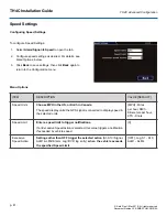
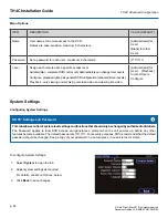
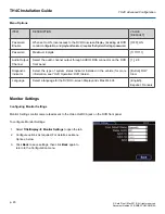
G-Sensor settings can be adjusted to fit specific requirements. Note that if thresholds are set too low and alarms are
enabled, many alarms may be generated. Details are provided below.
NOTE: Calibration
i
Summary of Contents for TH4C
Page 2: ......

