2)
If the blue wire is grounded when the alarm is armed, the blue wire circuit will be
unprotected until it becomes ungrounded. The alarm, however, will not trigger upon
arming if the Blue wire is grounded.
3)
If the Blue wire triggers the alarm, the disarm confirmation will change to four siren
chirps, four parking light flashes and the LED Status Light will flash 3 times between
pauses for 20 seconds to indicate that the alarm was triggered by negative instant trigger
wire.
Optional
Electronic
Sensor
Blue (-) Instant Trigger Wire.
Trunk
Light
Trunk
Pin
Switch
Hood
Pin
Switch
Note: Use IN4002
Diodes, Which May
Be Found At Most
Electronics Stores.
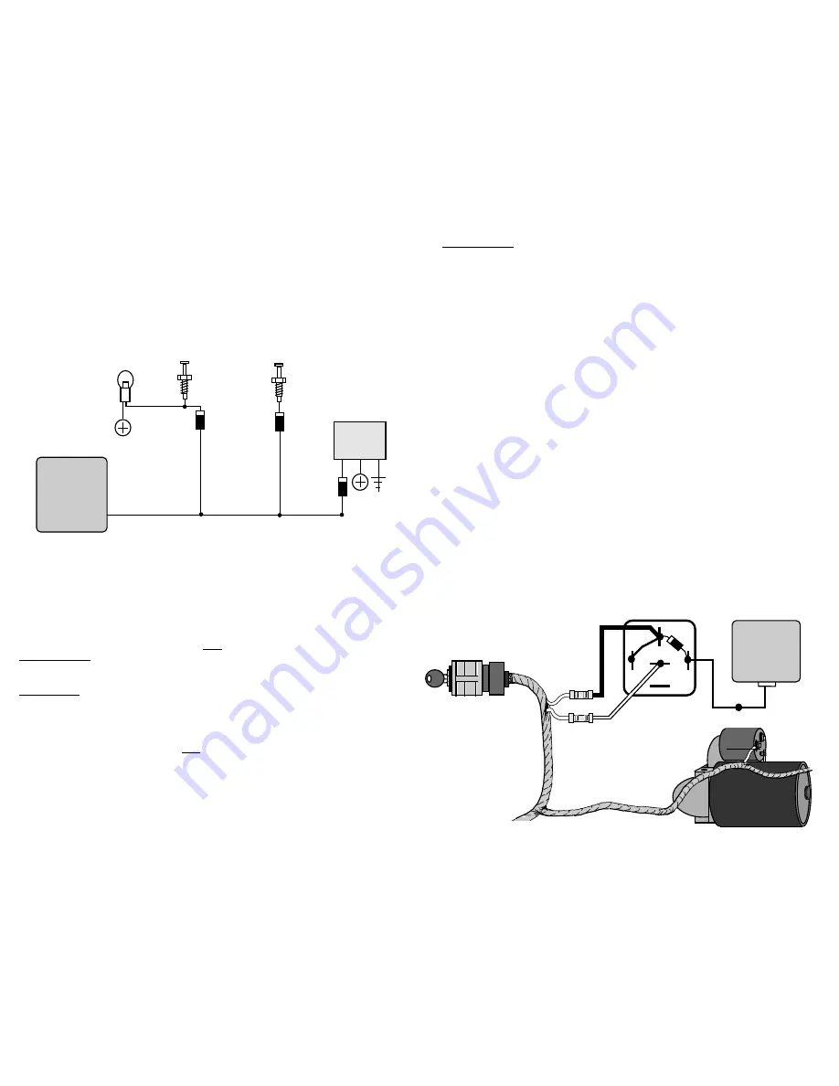
DIAGRAM FOR DIODE ISOLATING MULTIPLE BLUE WIRE USES
Alarm
Control
Unit
Page - 13
Continued Next Page
CONNECTION:
The included pin switch may be installed to provide this trigger circuit Or, if there are
existing switches (example: a light in the luggage compartment or a "Trunk Ajar" light in
the dash), the Blue wire may be connected directly, provided this is a negative ground
switching circuit. An indication of such a circuit is the wire having no voltage present when
the hood or trunk is open, and up to 12 volts when the hood or trunk is closed. This circuit
cannot be used with mercury switch types of hood or trunk lights. If the vehicle is equipped
with a usable trunk or hood circuit, locate the proper wire and splice the Blue wire directly
to the vehicle's wire.
When wiring more than one of the vehicle's circuits and/or additional circuits to this
wire, diode-isolation may be required to maintain each circuit's proper operation. An
example would be wiring a hood pin switch and trunk light switch together. Without
isolating, the trunk light will illuminate whenever the hood is raised. Also, diode-isolation
is necessary when combining electronic sensors together ,or, in the same circuit with pin
switches. See the diagram on the previous page.
Page - 14
Page - 15
Orange Grounded Output While Armed Wire:
The Orange wire is for an optional starter disable socket and relay. The function of
this wire is to provide a constant 500ma ground output whenever the alarm is armed. This
ground output supplies one side of the relay's coil. The other side of the relay coil will be
supplied with positive voltage from the ignition switch, but only if the ignition switch is
turned to the "start" position. If this occurs, the coil will energize, triggering the relay,
which in turn will open the starter circuit. The starter interrupt prevents the vehicle from
starting only if the alarm is armed (including while the alarm is triggered), and will draw
current from the vehicle's electrical system only if an attempt is made to start the vehicle.
CONNECTION:
To interrupt the vehicle's starter circuit, the starter wire must be located and cut. We
recommend that this be done as close to the ignition switch as possible. Use a voltmeter,
not a test light, to find the correct wire, which is the wire from the ignition switch to the
starter solenoid.
CAUTION! Improper use of a test light can cause deployment of the airbag, which may
result in bodily injury! Test lights can also damage expensive on-board computers and
associated sensors.
The starter wire will read 12 volts only when ignition key is in "start" position (crank-
ing
the engine). Cut this wire at a suitable location. Confirm that this is the correct wire by
turning the ignition switch to the "start" position. The starter should not engage. Now that
the starter wire has been cut, there are two sides - the ignition switch side and the starter
solenoid side. Connect the starter disable socket's Red wire to the ignition switch side, and
its White wire to the starter solenoid side. Be sure that you make good, solid electrical
connections as this is a high amperage circuit. Connect the alarm's Orange wire to the
Orange wire of the starter disable socket.
Continued Next Page
Ignition
Switch
Cutting The Vehicle's
Starter Wire Will Leave
Two Sides- The Ignition
Switch Side And The
Starter Solenoid Side.
Starter Disable Socket White
Wire To The Starter Solenoid
Side Of The Cut.
Starter
Solenoid
30
86 87a 85
87
Control
Module
Orange
Wire
Socket
Orange
Wire
Starter Disable Socket Red Wire To
The Ignition Switch Side Of The Cut.
Although a relay can be wired without using the starter disable socket, we recommend
using the socket. Besides being easier and faster than wiring a relay, the socket includes a
diode that prevents the relay from inductive lockup, which will prevent the vehicle from
being started. When wiring a relay without the socket, use the following diagram:
Alarm
Control
Unit
Page - 16


