ADS-B FDL-DB Dual Band Series
Installation Manual
Document No. 88552 Rev A
FFS Copyright © 2020 All rights reserved.
2-23
Serial Channels
PIN
SIGNAL
ELECTRICAL
I/O
DESCRIPTION
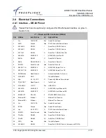
J1-50* TxD6-**
RS-422/RS-
232
I
Serial Port 6 Data Out-
2.5.6.1.1 RS-232 to RS-485/-422 Serial Converters
Some installations may require more RS-485/-422 serial interfaces than are available on the
FDL-DB Dual Band Series. For these installations, serial converters are available that can be
installed inline between the devices.
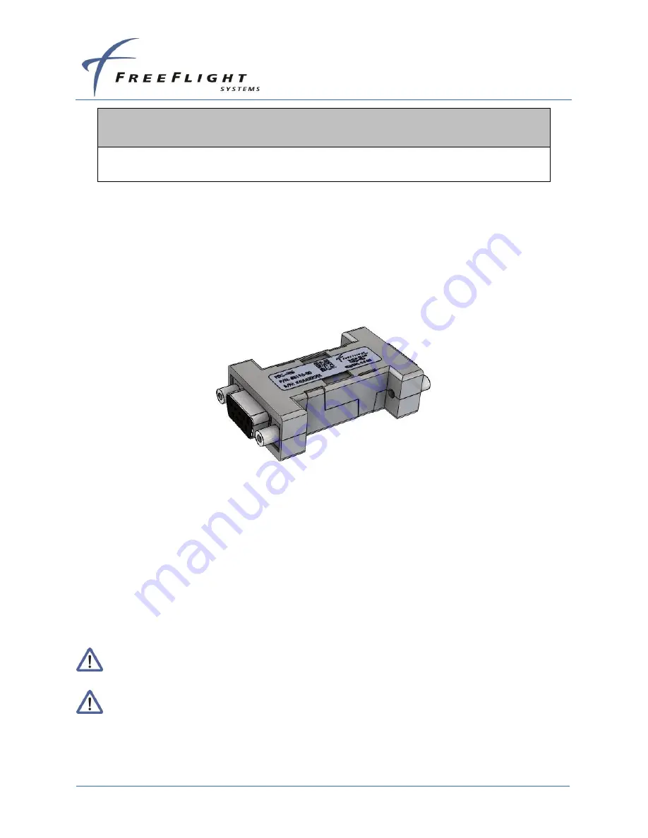
The FreeFlight Data Converters are used to convert an RS-232 port to RS-485 or RS-422. A
female DB-9 connects the converter to the FDL-DB Series wiring harness, while a male DB-9 is
connected to the other device.
Figure 4: FDC-485/422 Serial Converter
The FDC-485 can be used on the FDL-DB serial port 6 only when configured for RS-232
interface, using pins J1-50 and J1-8. The FDC-422 can be used on any FDL-DB serial port
configured for RS-232.
2.5.6.2 ARINC 429 Ports
Four ARINC 429 Input
Serial Interfaces
are available on ARINC capable FDL-DB Dual Band
models. The ARINC 429 Input channels are 429 IN 1, 429 IN 2, 429 IN 3, and 429 IN 4. The
ARINC capable FDL-DB Dual Band models have two ARINC 429 Outputs which are 429 OUT 1
and 429 OUT 2. The ARINC channels can be software configured for various label interfaces
and as either high-speed or low-speed.
Some ARINC functionality is available through a separate unit upgrade made
available at the time of installation.
Refer to SECTION 5 for additional detailed information about serial and ARINC
port configuration.
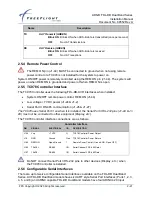
The ARINC 429
Serial Interface
pin connections are as follows:


