background image

ADS-B FDL-DB Dual Band Series 
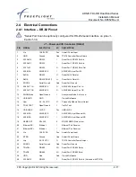
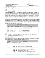
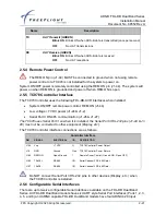
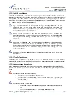
Installation Manual 
Document No. 88552 Rev A 


2-26 

FFS Copyright © 2020 All rights reserved.


2.5.8  Discrete Output 

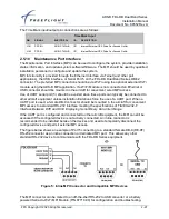
Two discrete outputs are available to provide UAT status and operational information to other 
equipment. The two discrete output connection pins are as follows: 

Discrete Outputs 

PIN 

SIGNAL 

ELECTRICAL 

I/O 

DESCRIPTION 

J1-34 

TX SUPPRESS 

Vin -1.5V 

L-Band Suppression Bus 

J1-53 

UAT STATUS 

Open/Ground 

ADS-B Status 

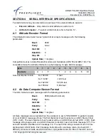
2.5.8.1 UAT Status Output 


Failure status of the UAT as well as loss of UAT position data must be annunciated 
to the pilot. The connected display or control head, such as the  TC978, typically 
provides  required  failure  annunciation.  This  discrete  can  be  used  to  drive  an 
annunciator when a display or TC978 is not installed or the MFD is not capable of 
annunciating status The UAT Status output is an active low, open collector output 
capable of sinking a maximum of 100 mA. The UAT status output indicates a UAT 
transmit or receive system failure when continuously grounded. UAT status output 
also indicates the loss of valid GPS data from an internal or external GPS. If the 
internal or external GPS is not functioning, reporting a failure, or reporting invalid 
GPS position data, this discrete will toggle between ground and open at a rate of 
approximately four times per second.  

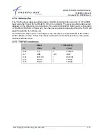
2.5.8.2 TX Suppression Output 

The TX Suppress output is for suppressing other L-band equipment during UAT transmissions. 
TX Suppress outputs a high (Vin 

– 1.5 V) only during UAT ADS-B message transmissions and 

is low otherwise. The TX Suppress output is typically connected to the transponder suppression 
bus. 


Receiver only installations do not need to connect to the transponder suppression 
bus. 

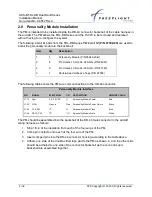
2.5.9  Time Mark Input/Output 

For the FDL-DB Dual Band Series, the Time Mark Input/Output is an RS-422 differential pair 
conforming to the ARINC 743A/B specification for the one pulse-per-second (PPS) input from 
an external GPS or output when the Transceiver/Receiver has an internal GPS. The Time Mark 
input/output from a GPS provides the timing synchronization for sending ADS-B messages. 


Time  Mark  from  a  GPS  provides  timing  synchronization  for  ADS-B  transmit 
messages. The Time Mark from an external GPS MUST be synchronized to UTC 
second epoch to operate correctly with the FDL-DB-XVR. 


Time Mark inputs from a single ended PPS source (e.g. Garmin Series 400/500 
GPS) must be properly interfaced to the differential interface for reliable operation. 

Summary of Contents for ADS-B FDL-DB Dual Band Series

Page 1: ... the purpose of the loan The document is to be returned to FreeFlight Systems upon request and or upon completion of the use for which it was loaned ADS B FDL DB Dual Band Series Installation Information Part Numbers P N 87334 XX XXXX Document No 88552 Disclaimer This manual revision is a controlled engineering release copy which is currently under review and pending TSO approval This document has...

Page 2: ......

Page 3: ...t Support for updated materials regarding your products For Product Support Repair or Sales please contact us directly or an authorized FreeFlight Systems Dealer Product Support Department Phone 1 254 662 0000 ext 503 Direct 1 254 662 7083 Toll Free 1 800 487 4662 ext 503 Email support freeflightsystems com Repair Department Phone 1 254 662 0000 ext 502 Direct 1 254 662 7082 Toll Free 1 800 487 46...

Page 4: ...ADS B FDL DB Dual Band Series Installation Manual Document No 88552 Rev A b FFS Copyright 2020 All rights reserved History of Revisions Dates of Revision are Revision A Initial Release August 20 2020 ...

Page 5: ...2 TC978 CONTROLLER 1 10 1 6 PARTS AND EQUIPMENT 1 11 1 6 1 FDL DB SERIES ITEMS 1 11 1 7 REQUIRED MATERIALS NOT SUPPLIED 1 12 1 7 1 LIST OF OTHER APPROVED GPS ANTENNAS 1 12 1 7 2 FT 9000 RAMP TESTER 1 13 SECTION 2 FDL DB DUAL BAND SERIES INTERFACES 2 14 2 1 UNPACKING AND INSPECTING EQUIPMENT 2 14 2 2 EQUIPMENT MOUNTING 2 14 2 2 1 FDL DB SERIES 2 15 2 2 2 TC978 CONTROLLER 2 16 2 3 COOLING REQUIREMEN...

Page 6: ...ER ELECTRICAL CONNECTIONS 2 30 2 6 1 TC978 INTERFACE DB 9 PINOUT 2 30 2 7 TC978 CONTROLLER INTERFACE DETAILS 2 30 2 7 1 POWER 2 30 2 7 2 REMOTE ON 2 30 2 7 3 TMAP BUS 2 30 2 7 4 ALTITUDE OUT 2 31 2 7 5 TC978 CONNECTIONS 2 31 2 8 PERSONALITY MODULE INSTALLATION 2 32 2 9 WIRING CONSIDERATIONS 2 34 2 10 UAT ANTENNA INSTALLATION 2 34 2 10 1 UAT ANTENNA GROUND PLANE 2 35 2 10 2 UAT ANTENNA CABLE 2 35 2...

Page 7: ...Configuration Details 5 16 5 2 MAINTENANCE PORT INTERFACE MPI HARDWARE CONFIGURATION 5 18 5 2 1 TERMINAL PROGRAM INTERFACE 5 18 5 2 1 1 Terminal MPI Network Connection Settings 5 18 5 2 1 2 Initial MPI Connection using the Telnet Remote Network Server Port 5 21 5 2 2 TERMINAL MAINTENANCE COMMANDS 5 22 5 2 2 1 help or Command 5 22 5 2 2 2 ads Command 5 24 5 2 2 3 bit Command 5 24 5 2 2 4 comm Comma...

Page 8: ...nnel X Interface Speed 5 43 5 3 2 13 ARINC OUT Chan 1 Data Type 5 44 5 3 2 14 ARINC OUT Chan 1 Interface Speed 5 44 5 3 2 15 Select Max Targets Output 5 45 5 3 2 16 GPS Certification 5 45 5 3 2 17 GPS NAC Velocity 5 46 5 3 2 18 Aircraft Length 5 46 5 3 2 19 Aircraft Width 5 46 5 3 2 20 GPS Reference Position Offset 5 47 5 3 2 21 Mode A C Receiver Sets Squawk 5 48 5 3 2 22 1090 MHz Receiver Install...

Page 9: ...2 2 FREEFLIGHT SYSTEMS 1203C GPS 7 1 7 3 EQUIPMENT COMPATIBILITY AND FUNCTIONS 7 1 SECTION 8 MAINTENANCE INTERFACE DIAGRAMS 8 1 SECTION 9 WARNING DISCLAIMER 9 1 SECTION 10 LIMITED WARRANTY 10 2 List of Figures FIGURE 1 TC978 CONTROLLER 1 7 FIGURE 2 FDL DB SERIES MOUNTING DIMENSIONS 2 15 FIGURE 3 TC978 DIMENSIONS 2 16 FIGURE 4 FDC 485 422 SERIAL CONVERTER 2 23 FIGURE 5 INLINE MPI CONNECTOR AND COMP...

Page 10: ... FDL DB SERIES SET TRAFFVELVAL COMMAND 5 34 FIGURE 31 FDL DB SET DISPLAYOUT COMMAND 5 35 FIGURE 32 GARMIN GNS 430W 530W DISPLAY AND GPS GTX 330 TRANSPONDER 7 1 FIGURE 33 CHELTON FLIGHTLOGIC DISPLAY GSL 71 CONTROLLER 7 2 FIGURE 34 ASPEN DISPLAY AND CONTROL GTX 327 TRANSPONDER 7 3 FIGURE 35 MODE A C TRANSPONDER TC978 CONTROLLER 7 4 FIGURE 36 GARMIN GNS 480 SL 70 TRANSPONDER TCAS 7 5 FIGURE 37 GARMIN...

Page 11: ...PUT ARINC LABELS 5 11 TABLE 10 TRANSPNDER CNTRL INPUT ARINC LABELS 5 12 TABLE 11 ADC FORMAT INPUT ARINC LABELS 5 13 TABLE 12 AHRS FORMAT INPUT ARINC LABELS 5 13 TABLE 13 ADC AHRS FORMAT INPUT ARINC LABELS 5 13 TABLE 14 TRAFFIC FORMAT INPUT ARINC LABELS 5 13 TABLE 15 ARINC 429 PORT OUTPUT CONFIGURATION SETTINGS 5 14 TABLE 16 ARINC 429 PORT OUTPUT SPEED CONFIGURATION SETTINGS 5 15 TABLE 17 TRAFFIC F...

Page 12: ...ADS B FDL DB Dual Band Series Installation Manual Document No 88552 Rev A viii FFS Copyright 2020 All rights reserved This page intentionally left blank ...

Page 13: ...nd the Federal Aviation Regulations FAR the FDL DB Series installations must meet the following requirements TSO C145d The conditions and tests required for TSO approval of this article are minimum performance standards Those installing this article on or in a specific type or class of aircraft must determine that the aircraft installation conditions are within the TSO standards TSO articles must ...

Page 14: ...nd the uncompensated latency is 0 seconds from current UTC second not including serial data transmission time The antenna installation must comply with the specifications in Section 2 10 for UAT antennas and Section 2 12 for GPS antennas Certified installations must be approved by a Supplemental Type Certificate STC or Type Certificate TC 1 1 2 FCC Warning RF Exposure Warning while this device is ...

Page 15: ...nt Surveillance Broadcast ARINC Aeronautical Radio Incorporated AS Associated ATC Air Traffic Control AWG American Wire Gauge bps bits per second C Celsius CSA Conflict Situation Awareness COMM Communications Receiver dB decibel dBm decibel milliwatts DC Direct Current DME Distance Measuring Equipment ETSO European Technical Standard Order ETX End of Transmission F Fahrenheit FAA Federal Aviation ...

Page 16: ...T Periodic Built In Test PC Personal Computer PED Personal Electronic Device PM Personality Module POST power on self test PPS pulse per second PRAIM Predictive RAIM RAIM Receiver Autonomous Integrity Monitoring RI Resolution Instruction RTS Request to Send Rx Receive SBAS Satellite Based Augmentation System SSI signal strength indication STC Supplemental Type Certificate TA Traffic Advisory TC Ty...

Page 17: ...d throughout this manual and their hierarchy is structured as shown below When an item applies to an entire section it will be identified at the beginning of the applicable section Otherwise it will immediately precede the information for which it applies Warnings are identified when failure to properly follow the instructions provided may cause serious injury to personnel or damage to equipment i...

Page 18: ...INC output port 1 or 2 In addition the internal GPS models can be configured to output GTX Remote GPS protocol data to interface with the GTX 330ES on the output serial port typically port 2 External GPS Input The FDL DB Series can connect to any FFS navigation protocol compliant GPS e g FFS 1201 Garmin series 400W 500W with GPS ADS B Plus interface through an RS 232 serial port or an ARINC 743A B...

Page 19: ...nterface The controller has a DB 9 connector for electrical interface and a static pressure port The controller contains a Liquid Crystal Display LCD with controls and built in Altitude Encoder TC978 low voltage input power is provided by the connected FDL DB Series equipment The TC978 uses serial interface to the FDL DB Series for control and also provides remote on off power control and serial a...

Page 20: ...s A1H ADS B equipment TSO C154c installations antenna diversity meaning a top and bottom antenna is required In Class A1S single antenna installations only one antenna bottom is used For airworthiness approval of ADS B out systems AC 20 165B single bottom mounted antenna TSO C154c Class A1S installations are allowed 1 4 3 GPS Antenna Requirements The FDL DB Series with internal GPS require a TSO C...

Page 21: ...1 Internal GPS models only PNs 87334 00 FX00 87334 00 FR00 FCC IDENTIFICATION T7YFDLDBXXXX SOFTWARE RTCA DO 178B Level C HARDWARE RTCA DO 254 Level C PHYSICAL DIMENSIONS Height 1 7 in 43 18 mm Width 5 0 in 127 mm Depth 5 5 in 139 7 mm WEIGHT 0 94 lb 426 g with no internal GPS 1 05 lb 476 g with internal GPS OPERATING TEMPERATURE 40 F to 158 F 40 C to 70 C STORAGE TEMPERATURE 67 F to 185 F 55 C to ...

Page 22: ...et Discrete Inputs Input 3 Air Ground Traffic Test and Anonymous Mode Discrete Outputs Output 2 Transmit Suppression and UAT Status GPS Output Output Serial RS 232 Internal GPS models only P N 87334 00 FX00 and 87334 00 FR00 1 5 2 TC978 Controller Specification Characteristics ENVIRONMENTAL COMPLIANCE See SECTION 3 TSO COMPLIANCE C154c Incomplete System C88b ETSO COMPLIANCE C88a SOFTWARE RTCA DO 1...

Page 23: ...ver without GPS 88133 00 1 FDL DB XVR RX Installation Kit optional 87349 1 TC978 Controller optional 86964 1 TC978 Installation Kit optional 87002 20 1 Personality Module Installation Kit Dualband optional 87003 00 1 Blade Type Antenna Installation Kit optional 87004 00 1 Ball and Stick Type Antenna Installation Kit optional 87360 10 1 TSO C144 AERO ANT GPS Type Antenna Installation Kit optional 8...

Page 24: ...ty and velocity accuracy information properly interpreted by the FDL DB Series Note Only previously STC approved GPS receivers may be used FFS 1201 P N 84100 XX XXXX FFS 1203C P N 84327 5X XXXX Garmin Series 400 500 GPS with ADS B Plus Interface 1 7 1 List of Other Approved GPS Antennas The FDL DB Series with GPS may be installed with the following GPS antennas not supplied by FFS summarized below...

Page 25: ...stallation checkout troubleshooting and system operation verification as necessary it is recommended to use the FFS FT 9000 Ramp Tester The FT 9000 ramp tester kit part number can be ordered as an optional item using the part number specified in the table below Part Number Qty Description 87579 00 1 FT 9000 ADS B RAMP Tester Kit Figure 2 FT 9000 Ramp Tester System ...

Page 26: ...e the GTX 330 327 32 33 and SL 70 R should be connected via an FDL DB XVR serial port to control Mode A code and IDENT Mode A C transponders without serial control out can use the FDL DB XVR internal Mode A receiver configuration setting which receives on board Mode A C transponder transmissions to automatically set Mode A code and IDENT control data transmit Mode A receive is not compatible with ...

Page 27: ...e cabin or an avionics bay Select a position in the aircraft that is away from any high external heat source The FDL DB Series is not a significant heat source itself Avoid sharp bends and placing the cables too near to the aircraft control cables Secure the FDL DB Series on a flat surface according to the mounting requirements illustrated below in and in the installation drawing in SECTION 7 Figu...

Page 28: ... 2 25 in instrument cut out first clip the two mounting adapters to the Controller The Controller should then be mounted using the four LONG screws provided If using the FFS compact cutout you do not need the mounting adapters The Controller should be mounted using the four SHORT screws provided If alternate screws are required please note that the mounting thread in each case is 4 40 Figure 3 TC9...

Page 29: ...Port Ground 10 429 OUT 1A ARINC 429 O ARINC 429 Output Port 1A 11 429 OUT 1B ARINC 429 O ARINC 429 Output Port 1B 12 ANON Mode Open Ground I Anonymous Mode Active Low 13 USB GND GND Ground Reference 14 Vpm 3 0 3 6 VDC O Personality Module Power Output 15 TRAF TEST Open Ground I Traffic Test 16 USB VBUS 5VDC Pwr USB 5VDC 17 429 IN 3A ARINC 429 I ARINC 429 Input Channel 3A 18 429 IN 3B ARINC 429 I A...

Page 30: ...Port Transmit 43 RTRN Ground Gnd Aircraft Power Return 44 REM ON Open Ground I Remote Power Control Ground ON Open OFF 45 232 TxD2 RS 232 O Serial Port 2 RS 232 Data Out 46 429 IN 1A ARINC 429 I ARINC 429 Input Port 1A 47 429 IN 1B ARINC 429 I ARINC 429 Input Port 1B 48 429 IN 2B ARINC 429 I ARINC 429 Input Port 2B 49 TxD6 RS 422 O Serial Port 6 Data Out 50 TxD6 RS 422 RS 232 I Serial Port 6 Data ...

Page 31: ...Use a 2 Amp circuit breaker for power supply protection Power input resides on the following pins Power Input PIN SIGNAL ELECTRICAL I O DESCRIPTION J1 1 Vin 10 40 VDC Pwr Aircraft Power Input J1 22 Vin 10 40 VDC Pwr Aircraft Power Input J1 23 RTRN Ground Gnd Aircraft Power Return J1 43 RTRN Ground Gnd Aircraft Power Return J1 44 REM ON Open Ground I Remote Power Control Ground ON Open OFF REM_ON m...

Page 32: ...automatically re configure the FDL DB XVR if it is replaced in the installation However if the TC978 Controller is replaced in an installation without the PM the FDL DB XVR MUST be re configured The PM connections are on the following pins Personality Module Interface PIN SIGNAL ELECTRICAL I O DESCRIPTION J1 14 Vpm 3 0 3 6 VDC O Personality Module Power Output J1 36 GND Ground Gnd Personality Modu...

Page 33: ...Low voltage 7 VDC power J1 24 J1 2 Serial Port 3 RS 485 communication J1 26 J1 27 The TC978 uses Serial Port 3 so when it is installed the Serial Port 3 RS 232 pins J1 24 J1 29 must not be connected to other equipment Display etc The TC978 Controller interface connections are as follows Controller Interface PIN SIGNAL ELECTRICAL I O DESCRIPTION J1 24 Vcp 7 VDC O TC978 Controller Power Output J1 2 ...

Page 34: ... be software configured for various protocols and baud rates Serial Port 6 can be optionally configured for RS 232 serial interface on pins J1 8 and J1 50 The UART style Serial Interface pin connections are as follows Serial Channels PIN SIGNAL ELECTRICAL I O DESCRIPTION J1 4 232 RxD1 RS 232 I Serial Port 1 RS 232 Data In J1 5 232 TxD1 RS 232 O Serial Port 1 RS 232 Data Out J1 3 232 RxD2 RS 232 I ...

Page 35: ...ure 4 FDC 485 422 Serial Converter The FDC 485 can be used on the FDL DB serial port 6 only when configured for RS 232 interface using pins J1 50 and J1 8 The FDC 422 can be used on any FDL DB serial port configured for RS 232 2 5 6 2 ARINC 429 Ports Four ARINC 429 Input Serial Interfaces are available on ARINC capable FDL DB Dual Band models The ARINC 429 Input channels are 429 IN 1 429 IN 2 429 ...

Page 36: ...ARINC 429 I ARINC 429 Input Port 4A J1 60 429 IN 4B ARINC 429 I ARINC 429 Input Port 4B J1 10 429 OUT 1A ARINC 429 O ARINC 429 Output Port 1A J1 11 429 OUT 1B ARINC 429 O ARINC 429 Output Port 1B J1 58 429 OUT 2A ARINC 429 O ARINC 429 Output Port 2A J1 59 429 OUT 2B ARINC 429 O ARINC 429 Output Port 2A 2 5 7 Discrete Inputs Input pins are pre configured active low Three discrete inputs are availab...

Page 37: ...nd air pressure altitude airspeed etc data Rotorcraft Installations The FDL DB Dual Band Series sufficiently validates an Air Ground input discrete based on collective position or collective position combined with oil pressure no low engine RPM airspeed etc to ensure false On Ground indications are not transmitted during auto rotation training and other unusual conditions Automatic air ground dete...

Page 38: ...l or external GPS is not functioning reporting a failure or reporting invalid GPS position data this discrete will toggle between ground and open at a rate of approximately four times per second 2 5 8 2 TX Suppression Output The TX Suppress output is for suppressing other L band equipment during UAT transmissions TX Suppress outputs a high Vin 1 5 V only during UAT ADS B message transmissions and ...

Page 39: ...raft for convenient wired MPI access Use of UART serial port 5 should be avoided since these ports can typically be connected to other aircraft equipment unless installation limitations force the use of a UART port When a UART port is used a female DB 9 connector should be mounted in the aircraft for convenient MPI access to a standard RS 232 interface meeting the specifications of TIA EIA 232 F I...

Page 40: ...ly for connection to a computer s USB connection USB Interface PIN SIGNAL ELECTRICAL I O DESCRIPTION J1 16 USB VBUS 5VDC Pwr USB 5VDC J1 38 USB D USB Serial I O USB Data or U5 TX TTL Serial J1 37 USB D USB Serial I O USB Data or U5 RX TTL Serial J1 35 GND Ground G USB Ground 2 5 10 2 Ethernet Interface The 10 100 Ethernet interface is a standard interface that connect to a computer Ethernet port E...

Page 41: ...ADS B FDL DB Dual Band Series Installation Manual Document No 88552 Rev A FFS Copyright 2020 All rights reserved 2 29 ...

Page 42: ...ller Serial Bus 4 ALT_OUT RS 232 O Pressure Altitude Out 5 Reserved 6 GND Ground Gnd Signal Common 7 REM ON Open Gnd O Remote Power Control Ground ON Open OFF 8 POWER 6 10 VDC Pwr Controller Power 9 GND Ground Gnd Controller Power Common 2 7 TC978 Controller Interface Details 2 7 1 Power Do NOT connect to aircraft input power The TC978 uses 5 5 10 volts from the FDL DB XVR typically 7 volts 2 7 2 ...

Page 43: ...on If an external Altitude Air Data Input is configured to a FDL DB XVR ARINC or Serial port then the pressure altitude data output from the TC978 will pass through data from that sensor If an Altitude Air Data Input is not configured then the pressure output defaults to the TC978 built in altitude encoder If used this output must feed the aircraft transponder so they share the same altitude sourc...

Page 44: ...6 The following table shows the PM wire color connections to the DB 44 connector Personality Module Interface PIN SIGNAL ELECTRICAL I O DESCRIPTION PM WIRE COLOR J1 14 Vpm 3 0 3 6 VDC O Personality Module Power Red J1 36 GND Ground Gnd Personality Module Power Return Black J1 55 CLK_PM I2 C O Personality Module Clock Blue J1 56 DATA_PM I2 C I O Personality Module Data White The PM should be assemb...

Page 45: ...ADS B FDL DB Dual Band Series Installation Manual Document No 88552 Rev A FFS Copyright 2020 All rights reserved 2 33 Figure 6 Personality Module Assembly ...

Page 46: ... operation The following table gives guidelines for typical aircraft hook up wire Different brands may vary check your supplier for details Gauge Milliohm ft Length for 0 5 ohm 24 AWG 30 2 33 2 ft An alternative to a harness built from individual wires particularly for a long cable run is to use a multi core cable Aviation grade cable with six or more cores is often more expensive than the individ...

Page 47: ...ractical ground plane is a square around 5 25 in per side as the size increases the performance may actually decrease but will improve by increasing the ground plane to 30 5 in on each side Anything much larger than that size is unlikely to show significant further improvement The thickness of the material used to construct the ground plane is not critical providing it is sufficiently conductive A...

Page 48: ... manufacturer s instructions Selecting appropriate GPS antenna locations is critical to the proper performance of the FDL DB Series Consider the following when selecting the Antenna location Typically a GNSS antenna is located forward or aft of the wings on top of the fuselage GNSS antennas must be installed to provide the widest unobstructed view of GNSS satellites Antenna placement on the airfra...

Page 49: ...nels as cautioned in Sec 14 1 of AC 20 138B GNSS equipment is particularly susceptible to out of band SATCOM emissions and in band inter modulation between multiple channel SATCOM installations GNSS equipment must not be installed in aircraft with multiple SATCOM channels unless the simultaneous use of interfering frequencies can either be prevented or demonstrated not to interfere with the operat...

Page 50: ...n the install kit 2 13 Department of Commerce Compliance The Department of Commerce Bureau of Export Administration s Revision of the Commodity Control List permits shipment of commercial GPS products for General Destination G Dest export only if they contain certain software provisions To comply with the G Dest category the FDL DB Series with GPS operates neither at altitudes above 18 287 meters ...

Page 51: ...Time Operating High Temperature Ground Survival Low Temperature Ground Survival High Temperature Loss of Cooling Altitude Decompression Overpressure 4 5 2 4 5 4 4 5 1 4 5 3 4 5 1 4 5 3 4 5 5 4 6 4 6 2 4 6 3 40ºF 40 C C4 158ºF 70 C C4 40ºF 40 C C4 158ºF 70 C C4 67 F 55 C C4 185 F 85 C C4 Z N A No cooling required 50 000ft D 50 000ft A 15 000ft A Temperature Variation 5 B Humidity 6 A Operational Sh...

Page 52: ...opyright 2020 All rights reserved Conditions Para Category DO 160G Emission of Radio Frequency Energy 21 MM Lightning Induced Transient Susceptibility 22 A2J3L3 shielded A2H3L3 unshielded Lightning Direct Effects 23 N A Icing 24 N A Electrostatic Discharge 25 A Fire Flammability 26 C ...

Page 53: ...ontents A L T 1 2 3 4 5 c r Some examples include ALT 00000 0 feet ALT 1200 1200 feet ALT 62505 62 505 feet ALT 05604 5 604 feet 4 2 Air Data Computer Sensor Format The ADC format accepts messages with the following parameters Baud 9600 default minimum Parity None Start Bit 1 Data Bits 8 Stop Bit 1 Update Rate 1 msg sec Air Data messages are accepted when the serial port is set to ENCODER A packet...

Page 54: ... 2DH The table below lists the message items used by the FDL DB XVR Additional items may be in the message but they are not used by the units Item Format Contents Description ZBddd True Air Speed ddd knots 40 to 600 ZDsdddd Pressure Altitude s sign dddd tens of feet 100 to 5999 ZKsddd Vertical Speed s sign ddd tens of feet minute 600 to 600 ZRddd Packet Checksum ddd number 0 to 255 ...

Page 55: ...l not accept control inputs Serial port 2 is typically used for control input Remote network server ports 1 and 2 can also be used for control input Control Input is NOT required for receive only systems GPS Input The FDL DB Dual Band Series requires position velocity time and integrity data from a GPS sensor The internal GPS or an external GPS must be configured to provide this data GPS Input is ...

Page 56: ...nterfaces All data interface types except Display Output from the table above can be configured to one and only one Serial or ARINC port If multiple Serial ARINC ports are set to the same data interface type then only one port is actually configured and other settings of the same data interface type are ignored The data interface order of precedence is as follows 1 ARINC 429 ports take precedence ...

Page 57: ...I The ADS B MPI application includes additional and improved automated status feedback and automatic enforcement of the above configuration rules that is not available when configuring the system with the TC978 or the simple terminal program MPI interface The ADS B MPI application requires use of either a Serial to Wi Fi Transceiver FWF 125 P N 86943 00 properly connected to Port 5 or the recharge...

Page 58: ...utput is TSO C145c Class Beta 1 certified and can be used as an ADS B position source or navigation source GPS FFS 5 GPS FreeFlight GPS Input GPS position velocity time and integrity data input Format for the FFS 1201 or other sensors that support the FFS Chelton Protocol Typically configured on port 1 GPS ADS B Plus 5 GPS GNS ADS B GPS Input GPS position velocity time and integrity data input For...

Page 59: ...ttings on a system with a TC978 installed then the TC978 will not accept inputs and will instead mirror the control inputs coming from the transponder or the display If control input is lost from another device for 60 seconds then the TC978 will take over the role as the primary controller 7 The GTX 330 outputs its own call sign in a single message at startup When the FDL DB XVR is powered on firs...

Page 60: ... 3 MX 20 MX 20 Display Output Ownship data traffic reports and FIS B data Format for the MX 20 The corresponding serial input port can be configured to Disp Cntrl at the same baud rate to enable display control input 3 4 1 Maintenance port setting names listed first with TC978 configuration menu setting names in parenthesis 3 Setting Disp Cntrl for an input port must correspond to setting a displa...

Page 61: ...rmat for devices that output the Labels listed in the ADC AHRS table below AHRS AHRS Heading Input True Heading data input Format for devices that output the True Heading Label 314 GPS 743 GPS GPS Input GPS position velocity time and integrity data input Format for the FFS 1203C or other sensors that output the ARINC 743A B labels listed in GPS 743 Labels Table below and also outputs a Time Mark t...

Page 62: ...id 142 Velocity Vertical FOM 145 Velocity Horizontal FOM 140 UTC fine 141 UTC fine fraction 150 UTC 352 FreeFlight Maintenance Data content must conform to the navigation data block of ARINC 743A B Table 10 Transpnder Cntrl Input ARINC Labels Label Description 016 TCAS ATC Control Squawk Code and IDENT only 031 ATCRBS Control Squawk Code and IDENT only 233 Call Sign Flight ID Characters 1 2 234 Ca...

Page 63: ...RS Format Input ARINC Labels Label Description 203 Pressure Altitude 210 Airspeed 212 Altitude Rate 314 True Heading Table 14 Traffic Format Input ARINC Labels Label Description 274 TCAS Output Receiver health in System Status 350 Fault Summary Traffic Advisory TA only mode set in Resolution Instruction RI field 314 True Heading 357 Request to Send RTS and End of Transmission ETX words for Intrude...

Page 64: ... Configuration Settings Setting 1 Interface Description UNUSED Not Used No connection to ARINC 429 output port Traffic Traffic Display Output Ownship data and traffic intruder data format for displays that receive the ARINC 735A B Traffic Labels listed in the table below GNS 400 500 series GNS 480 1 Maintenance port setting names listed first with TC978 configuration menu setting names in parenthe...

Page 65: ... servers can send output on UDP in three ways Broadcast IP address of a specific client IP address of the originator of the most recently received message on the UDP listener port Note there is no output until a message is received to initialize the destination address and port 5 1 1 5 2 TCP Connection Network servers can connect and send to up to a maximum of 10 TCP clients from a pool shared bet...

Page 66: ...rver port input data formats Table 19 Network Server Port Input Configuration Settings Setting Interface Description cntrl enable Control Input Squawk Code IDENT Call Sign and mode standby alt inhibit Enables display control from a GMX 200 or other displays using the GDL FDL protocol The corresponding network server output port must be configured to Traffic Alert to enable display control input 2 ...

Page 67: ...fic data and FIS B data Format for sending unprocessed uncorrelated and un prioritized raw ADS B messages Traffic must be processed in another device to meet TSO C195a ASSAP installation requirements The Network server port functionality can also be set to MAINT to enable configuration and maintenance modes for the FDL DB Series systems See set netserver command information in section 5 2 2 12 3 ...

Page 68: ... a MPI connection made via serial port or Wi Fi depending on the interface device used The terminal setup should be set to Local Echo checked Figure 8 Tera Term Terminal Setup 5 2 1 1 Terminal MPI Network Connection Settings A Network connection to the FDL DB series systems can be made on the PC or Android tablet running the ADS B MPI app The typical Tera Term TCP settings for the Network connecti...

Page 69: ...ADS B FDL DB Dual Band Series Installation Manual Document No 88552 Rev A FFS Copyright 2020 All rights reserved 5 19 Figure 9 Tera Term Network Connection Settings using Telnet ...

Page 70: ...ADS B FDL DB Dual Band Series Installation Manual Document No 88552 Rev A 5 20 FFS Copyright 2020 All rights reserved Figure 10 Network Hardware Connections ...

Page 71: ...emote Network Server Port 5 2 1 2 Initial MPI Connection using the Telnet Remote Network Server Port Once connected to the MPI with a Remote TCP UDP network connection press the Enter key once to remove the maintenance lockout The following prompt should be displayed RANGR RX FDL DB RX RANGR XVR FDL DB XVR Figure 12 Example Tera Term Network Connection Settings using Telnet ...

Page 72: ...ut help or Display command help info Display info S N operation hours versions etc Reset Reset and restart the unit rxstatus Display receiver status info continuous set item value Set a configuration item s value stop Stop continuous data outputs cnfg defaults Reset configuration to defaults All screenshots in the following sections are taken from the FDL 978 XVR configuration with no feature upgr...

Page 73: ...ADS B FDL DB Dual Band Series Installation Manual Document No 88552 Rev A FFS Copyright 2020 All rights reserved 5 23 Figure 13 FDL DB Series Help Menu ...

Page 74: ... DB Series ads menu 5 2 2 3 bit Command This command displays built in test information about the FDL 978 Series health Example output is displayed below Figure 15 FDL DB Series bit menu 5 2 2 4 comm Command This command continually displays serial port communication status information enabled disabled status and receive and transmit byte count and errors The data is updated once per second Exampl...

Page 75: ...DL DB Dual Band Series Installation Manual Document No 88552 Rev A FFS Copyright 2020 All rights reserved 5 25 Figure 16 FDL DB Series comm menu Type the stop command to stop updating and return to the prompt ...

Page 76: ...us altitude control status call sign transmit control status and vertical status Figure 17 FDL DB Series control menu 5 2 2 6 gps Command This command displays data which is being received from the GPS input Figure 18 FDL DB Series gps menu 5 2 2 7 info Command This command displays information such as Serial Number operation time and hardware and software version information about the FDL 978 Ser...

Page 77: ...e info command will display the FDL 978 s part number followed by the upgrade key part numbers 5 2 2 8 Reset Command This command causes the FDL DB Series to reboot Figure 20 FDL DB Series Reset command When using the USB maintenance interface press the Enter key three times to return to the maintenance interface When using the ethernet maintenance interface it maybe necessary to restart Tera Term...

Page 78: ...lomon errors RSErr x The third rxstatus section displays detailed traffic information This information includes total number of traffic targets being tracked and then detailed information about the ownship data being received and the 10 closest traffic targets The detailed traffic information includes address Addr address type Typ Call Sign Latitude Longitude altitude in feet Alt speed in knots Sp...

Page 79: ...nk message is received from the ground station for more than forty seconds Type the stop command to stop updating rxstatus and return to the prompt 5 2 2 10 cnfg Command This command displays configurable information such as the serial port settings protocol and baud rate the ICAO address and the VFR Call Sign Example output is displayed below Figure 22 FDL DB Series cnfg menu ...

Page 80: ...tallation Manual Document No 88552 Rev A 5 30 FFS Copyright 2020 All rights reserved 5 2 2 11 cnfg defaults Command This command resets all configuration values to default factory settings Figure 23 FDL DB Series cnfg defaults command ...

Page 81: ...FDL DB Series set help menu 5 2 2 12 1 set hostname Command This command sets the Hostname of the FDL DB Series system by which it can identified with on the host network Help on this command is displayed by entering set hostname Example set hostname output is displayed below Figure 25 FDL DB Series set hostname help menu 5 2 2 12 2 set net Command This command is used to modify network related co...

Page 82: ...rved Figure 26 FDL DB Series set net help menu 5 2 2 12 3 set netserver Command This command is used to modify network server related configuration settings such as client ip and network server functionality Help on this command is displayed by entering set netserver Example set netserver output is displayed below ...

Page 83: ...e maximum number of targets to be sent on any configured serial or ARINC 429 port configured for traffic display output This is typically used to limit the number of traffic targets for displays that can process a large number of traffic targets Figure 28 FDL DB Series set max trgs command 5 2 2 12 4 2 set cheltonCSA Command This command enables disables the Conflict Situational Awareness CSA bit ...

Page 84: ...me traffic states low speed ground will still cause the NACv 0 track velocities to be invalidated and sent to the display as non directional traffic Setting this parameter to disable turns off all DO 317A TSO C195a velocity validation invalidation and passes the track s velocity data to the display as directional traffic This parameter should only be set to disable for legacy non TSO C195a display...

Page 85: ...e Configuration Mode during flight The system should be configured during initial system installation by a qualified technician The configuration items list in Section Error Reference source not found should be used to document the system installation for future reference To view or change these settings you must enter TC978 Configuration Mode The configuration setup screen is the first thing disp...

Page 86: ...78 Controller displays the following typical messages in a quick sequential order 5 3 2 FDL DB XVR Configuration Mode Operation The following paragraphs detail the setup modes available for configuring the FDL DB XVR Configuration items can be changed using the CODE knob and the ENT button Pressing the FN button advances to the next configuration item ...

Page 87: ...uawk Code In the USA the VFR Squawk Code is 1200 and in most parts of Europe the VFR Squawk Code is 7000 The default VFR Squawk Code cannot be changed in flight and can only be set in the configuration mode The VFR Squawk Code is a 12 bit number and is represented as a four character octal number The CODE knob is used to change each character as required Each character of the Squawk Code is a numb...

Page 88: ...iguration mode 5 3 2 4 Groundspeed Threshold Groundspeed threshold can be used to help determine and verify the ON GROUND condition for transmitting ON GROUND ADS B message types for Light Fixed Wing aircraft types only The FDL DB XVR uses the ground speed threshold configuration to determine a maximum ON GROUND speed There are 10 options to select groundspeed threshold Unknown 30 knots 40 knots 5...

Page 89: ...DE knob either clockwise or counterclockwise to display the options above and select the correct aircraft category Once selected press the ENT button to confirm your selection and move to the next configuration item in the setup mode 5 3 2 6 Squat Switch Type Rotate the CODE knob either clockwise or counterclockwise to display the options above and select the correct Squat Switch type Once selecte...

Page 90: ... Channel 6 Not Used Altitude Encoder GPS FreeFlight Control Panel TMAP Remote GPS GNS ADS B TIS FIS Air Data Computer Refer to Section 5 1 1 1 for details on selecting serial input settings The TC978 will not accept control inputs and will mirror the transponder or primary controller If communication with the primary controller is lost for 60 seconds then the TC978 will assume the role of the cont...

Page 91: ...ing the serial input baud rate for each channel data type 4800 9600 19200 38400 57600 115200 230400 The display screen is as shown below with one of the options from the list above Rotate the CODE knob either clockwise or counterclockwise to display the options above and select the correct serial input speed Once selected press the ENT button to confirm your selection and move to the next configur...

Page 92: ...lect the correct serial output type Once selected press the ENT button to confirm your selection and move to the next configuration item in the setup mode If Not Used is selected then the serial output line speed configuration mode is not displayed and the next configuration mode item is displayed 5 3 2 10 Serial OUT Channel X Line Speed X channel number The following options are offered for selec...

Page 93: ...tions above and select the correct ARINC input type Once selected press the ENT button to confirm your selection and move to the next configuration item in the setup mode If Not Used is selected then the ARINC input line speed configuration mode will not be displayed and the next configuration mode item will be displayed 5 3 2 12 ARINC IN Channel X Interface Speed X channel number The following op...

Page 94: ...ove and select the correct ARINC output type Once selected press the ENT button to confirm your selection and move to the next configuration item in the setup mode If Not Used is selected then the ARINC output line speed configuration mode is not displayed and the next configuration mode item is displayed 5 3 2 14 ARINC OUT Chan 1 Interface Speed The following options are offered for selecting the...

Page 95: ...e to the next configuration item in the setup mode 5 3 2 16 GPS Certification The FDL DB XVR needs a valid GPS source so that aircraft position can be transmitted in its ADS B message The GPS source is usually certified to a RTCA DO 178B software level as mandated by the governing FAA TSO The following GPS software certification levels can be selected Uncertified Level D Level C Level B The displa...

Page 96: ...ec and 3 meters sec are permanent set at installation in the software GPS Auto is automatically set from the velocity FOM VFOM data from the GPS unit The NACv value is hard coded to broadcast no better than 3 meters sec even if GPS Auto is selected For FDL 978 series units with internal GPS set GPS NAC Velocity to GPS Auto For external position sources contact the manufacturer to obtain the releva...

Page 97: ...Set here is selected then options for manually entering the GPS antenna reference offset are displayed as below It is recommended to use the Manual Set Here option to set the GPS GNSS antenna reference position for all installations GPS Reference Position is measured from the GPS antenna location to the lateral distance from centerline and longitudinal distance from the most forward part of the ai...

Page 98: ...h a Mode A C transponder that does not have digital control output This allows the internal or external transponder monitor sniffer antenna to detect the squawk code being broadcast from the airplane and use this same one in the ADS B Out messages Set to disable when using a transponder with digital control output The display screen is as shown below with one of the options from the list above Rot...

Page 99: ...er Yes or No and select the correct option Once selected press the ENT button to confirm selection and move to the next configuration item in the setup mode All FDL 978 series units except the TXL contain a UAT receiver and should select the Yes option 5 3 2 24 UAT Antenna Diversity The default value is set at Bottom Only It is recommended to install dual antennas for maximum coverage Top only ins...

Page 100: ...tup mode 5 3 2 25 UAT Antenna Check Ground Confirm if the UAT antenna s used have a ground connection that allows the FDL DB XVR to check if the antenna is installed by selecting the YES or No options Rotate the CODE knob either clockwise or counterclockwise to display either Yes or No and select the correct option The display is as shown below Once selected press the ENT button to confirm selecti...

Page 101: ...der in the TC978 Controller is accurately calibrated in the factory to be within 50 feet of the applied pressure altitude at all altitudes whereas the allowed error in the primary altimeter increases with altitude and above 18 000 feet the altimeter error alone may exceed 125 feet It is therefore possible that the combination of the allowed errors in the encoder and the primary altimeter may excee...

Page 102: ... setup mode And skipping over the configuration modes until reaching the calibrate altitude encoder section When you are in the calibrate altitude encoder setup mode the display shows the following information 4 Rotate the CODE knob either clockwise or counterclockwise to display either Yes or No and select the correct option Once selected press the ENT button to confirm your selection and move to...

Page 103: ...ill move to the test altitude screen which is the next configuration item in the setup mode To complete the testing you should leave the front controller screen displaying the encoder altitude and exercise the altitude on the static test set across the altitude range of the aircraft The display will be as shown above for pressure reported Use at least 10 test points and verify that in each case th...

Page 104: ...oting No LED Activity No power Verify power is turned on Check power connections to unit TX LED not active Unit is not transmitting ADS B messages Check antenna connections Check Controller Warning messages RX LED not active Unit is not receiving ADS B messages Check antenna connections Check Controller Warning messages ST LED is on A fault with the unit Check Controller Warning messages ST LED is...

Page 105: ...Failure PBIT Bottom Antenna Not Connected If DC ground check configured PBIT Top Antenna Not Connected If DC ground check configured PBIT RF Transmission Power Too Low PBIT GWSS not communicating or reporting fault PBIT RF Transmit Power Supply Low PBIT Internal Temperature Too High PBIT RF Transmit Reverse Power Too High PBIT Nominal Message Rate not once per second PBIT Broadcast monitor failure...

Page 106: ... Unlock Transceiver Diagnostic Timing Fault Tx Fault UAT Transceiver fault Tx Power Low UAT Transceiver power low during transmit Tx PSU High UAT Transceiver power supply output too high Tx PSU Low UAT Transceiver power supply output too low Squitter Fail System Diagnostic Remote Hot FDL DB Series internal temperature too high No ADS B Pos The unit is not receiving digital serial communication fro...

Page 107: ...the FDL DB XVR Turn power off for several minutes then back on Return for maintenance if problem persists No ADS B Pos The unit is not receiving digital serial communication from the GPS Verify GPS is functioning Verify GPS Port Configuration and speed Verify GPS communication connection GPS Fault GPS has reported no available position or a fault Verify GPS is functioning Verify GPS Antenna Cable ...

Page 108: ... Air Ground input will vary on each aircraft depending on the equipment installed Refer to the aircraft manual to determine the appropriate input signal to the FDL DB Series Light Aircraft can refer to Section 2 5 7 1 for additional notes on Air Ground determination All ports except MPI not connected to equipment should be set to UNUSED The FDL DB Series requires an approved STC before installatio...

Page 109: ...l Out 3 TMAP 38400 Serial In 4 Alt Encoder 9600 Serial In 5 MAINT 115200 Serial Out 5 Traffic Alert 115200 Serial In 6 UNUSED 115200 RS 232 Serial Out 6 UNUSED 115200 RS 232 ARINC In 1 UNUSED low ARINC In 2 UNUSED low ARINC Out 1 Traffic high NOTES 1 ALL WIRES ARE 24 AWG MINIMUM UNLESS OTHERWISE NOTED AND MUST BE MIL W 16878E 4 OR EQUIVALENT 2 CONNECT TWISTED PAIR SHIELDED WIRE GROUNDS TO SERIAL G...

Page 110: ...rial Out 3 TMAP 38400 Serial In 4 UNUSED 9600 Serial In 5 MAINT 115200 Serial Out 5 Traffic Alert 115200 Serial In 6 UNUSED 38400 RS 232 Serial Out 6 Traffic Alert 38400 RS 232 ARINC In 1 UNUSED low ARINC In 2 UNUSED low ARINC Out 1 UNUSED low NOTES 1 ALL WIRES ARE 24 AWG MINIMUM UNLESS OTHERWISE NOTED AND MUST BE MIL W 16878E 4 OR EQUIVALENT 2 CONNECT TWISTED PAIR SHIELDED WIRE GROUNDS TO SERIAL ...

Page 111: ...MAINT 115200 Serial Out 5 Traffic Alert 115200 Serial In 6 Disp Ctrl 115200 RS 232 Serial Out 6 Traffic Alert 115200 RS 232 ARINC In 1 UNUSED low ARINC In 2 UNUSED low ARINC Out 1 UNUSED low NOTES 1 ALL WIRES ARE 24 AWG MINIMUM UNLESS OTHERWISE NOTED AND MUST BE MIL W 16878E 4 OR EQUIVALENT 2 CONNECT TWISTED PAIR SHIELDED WIRE GROUNDS TO SERIAL GROUND PINS OR AIRCRAFT GROUND WITH AS SHORT OF A CON...

Page 112: ...on CSA Enable disable Traffic Vel Validation enable Display Data Output traffic fisb XVR Mode xvr Serial In 1 Internal GPS 19200 Serial In 2 UNUSED 9600 Serial Out 2 UNUSED 9600 Serial In 3 TMAP 38400 Serial Out 3 TMAP 38400 Serial In 4 Alt Encoder 9600 Serial In 5 MAINT 115200 Serial Out 5 Traffic Alert 115200 Serial In 6 UNUSED 115200 RS 232 Serial Out 6 UNUSED 115200 RS 232 ARINC In 1 UNUSED lo...

Page 113: ...al GPS 19200 Serial In 2 GSL 71 9600 Serial Out 2 UNUSED 9600 Serial In 3 TMAP 38400 Serial Out 3 TMAP 38400 Serial In 4 Alt Encoder 9600 Serial In 5 MAINT 115200 Serial Out 5 MAINT 115200 Serial In 6 UNUSED 115200 RS 232 Serial Out 6 UNUSED 115200 RS 232 ARINC In 1 Traffic low ARINC In 2 UNUSED low ARINC Out 1 Traffic low NOTES 1 ALL WIRES ARE 24 AWG MINIMUM UNLESS OTHERWISE NOTED AND MUST BE MIL...

Page 114: ... UNUSED 9600 Serial In 3 TMAP 38400 Serial Out 3 TMAP 38400 Serial In 4 Alt Encoder 9600 Serial In 5 MAINT 115200 Serial Out 5 Traffic Alert 115200 Serial In 6 Disp Ctrl 38400 RS 422 Serial Out 6 MX 20 38400 RS 422 ARINC In 1 UNUSED low ARINC In 2 UNUSED low ARINC Out 1 UNUSED low NOTES 1 ALL WIRES ARE 24 AWG MINIMUM UNLESS OTHERWISE NOTED AND MUST BE MIL W 16878E 4 OR EQUIVALENT 2 CONNECT TWISTED...

Page 115: ...t 2 UNUSED 9600 Serial In 3 TMAP 38400 Serial Out 3 TMAP 38400 Serial In 4 Alt Encoder 9600 Serial In 5 MAINT 115200 Serial Out 5 Traffic Alert 115200 Serial In 6 UNUSED 38400 RS 422 Serial Out 6 Traffic Alert 38400 RS 422 ARINC In 1 UNUSED low ARINC In 2 UNUSED low ARINC Out 1 UNUSED low NOTES 1 ALL WIRES ARE 24 AWG MINIMUM UNLESS OTHERWISE NOTED AND MUST BE MIL W 16878E 4 OR EQUIVALENT 2 CONNECT...

Page 116: ...AP 38400 Serial Out 3 TMAP 38400 Serial In 4 Alt Encoder 9600 Serial In 5 MAINT 115200 Serial Out 5 Traffic Alert 115200 Serial In 6 UNUSED 115200 RS 232 Serial Out 6 UNUSED 115200 RS 232 ARINC In 1 UNUSED low ARINC In 2 UNUSED low ARINC Out 1 UNUSED low NOTES 1 ALL WIRES ARE 24 AWG MINIMUM UNLESS OTHERWISE NOTED AND MUST BE MIL W 16878E 4 OR EQUIVALENT 2 CONNECT TWISTED PAIR SHIELDED WIRE GROUNDS...

Page 117: ... Series Installation Manual Document No 88552 Rev A 7 2 Equipment Specific Installations 7 2 1 FreeFlight Systems 1201 GPS Figure 40 1201 Wiring Diagram 7 2 2 FreeFlight Systems 1203C GPS Figure 41 Figure1203C Wiring Diagram ...

Page 118: ......

Page 119: ...de A C Receiver X ARINC Transponder Controller X X X X Display Controller Aspen EFD 500 1000 X X Garmin MX 20 X X X X X Garmin GMX 200 X X X X X Chelton Flight Logic X ADS B Controller FreeFlight TC978 X X X X X Garmin GSL 71 X X X X 1 The GTX 330 only outputs the call sign in a single message when it is powered on The FDL DB Series must be powered on first in order to receive this message If the ...

Page 120: ...Chelton FlightLogic EFIS Software Version 6 0B Wi Fi Module All software versions Model 1201 GPS as a Position Source Software Version 0306 or later FAA approved version Model 1203C GPS Software Version 200B or later FAA approved version Garmin 400W 500W Series as a Position Source and or ADS B IN traffic source Main Software Version 5 03 or later GPS Software Version 5 00 or later ...

Page 121: ... 2020 All rights reserved 8 1 SECTION 8 MAINTENANCE INTERFACE DIAGRAMS The diagrams below provide a pictorial representation of these available options for accessing the maintenance port of the FDL DB XVR series Figure 42 Off the Shelf RS 232 to USB Converter Figure 43 Serial to Wi Fi MPI ...

Page 122: ...ADS B FDL DB Dual Band Series Installation Manual Document No 88552 Rev A 8 2 FFS Copyright 2020 All rights reserved Figure 44 Serial to Wi Fi Aircraft Module ...

Page 123: ...ADS B FDL DB Dual Band Series Installation Manual Document No 88552 Rev A FFS Copyright 2020 All rights reserved 8 1 This page intentionally left blank ...

Page 124: ......

Page 125: ...ense prevail when confronted with severe weather conditions The FDL DB Series provides traffic information that can be used as an aid for situational awareness only Pilots must rely on ATC guidance or visual rules for visual acquiring traffic and maneuvering their aircraft in traffic The FDL DB Series provides weather information that can be used as an aid for situational awareness only Weather in...

Page 126: ...UCT AND DISCLAIMS THE SAME FREEFLIGHT MAKES NO EXPRESS OR IMPLIED WARRANTY WITH RESPECT TO THE DESIGN ADEQUACY ACCURACY RELIABILITY SAFETY OR CONFORMANCE WITH GOVERNMENT STANDARDS OR REGULATION OF ANY FLIGHT PROCEDURE PRESCRIBED BY A GOVERNMENT AUTHORITY INCLUDING BUT NOT LIMITED TO ANY EXPRESS OR IMPLIED WARRANTY OF MERCHANTABILITY OR FITNESS FOR A PARTICULAR PURPOSE FURTHER FREEFLIGHT MAKES NO W...

Page 127: ... DB Dual Band Series Installation Manual Document No 88552 Rev A 7333 Interstate 35 South Robinson Texas 76706 3756 USA US 800 487 4662 International 1 254 662 0000 Made in USA This page intentionally left blank ...

Page 128: ......

Page 129: ...ADS B FDL DB Dual Band Series Installation Manual Document No 88552 Rev A For additional product information and specifications please visit our website at www freeflightsystems com ...

Reviews: