ADS-B FDL-DB Dual Band Series
Installation Manual
Document No. 88552 Rev A
2-28
FFS Copyright © 2020 All rights reserved.
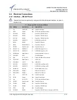
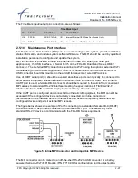
The table below shows the MPI DE-9F connections to Port 5 on the FDL-DB Series.
Table 1. MPI Pinout
MPI Connector
Port 5 (DB-62)
PIN
SIGNAL
PIN
SIGNAL
2
Tx
J1-54
232 TxD5
3
Rx
J1-32
232 RxD5
5
GND
J1-9
SGND4
An FFS fixed installation Serial-to-Wi-Fi Transceiver (P/N 86943-00) can be connected to Port
5. The MPI functionality can then be accessed wirelessly using the ADS-B MPI app.
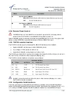
When Port 5 is configured and interfaced to other equipment (e.g. displays etc.)
the connections to the configured device must be temporarily disconnected to use
the port for MPI purposes.
2.5.10.1
USB Interface
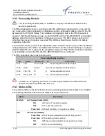
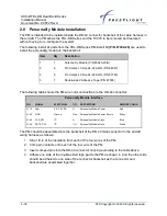
The standard USB interface that can be used as an MPI
Only
for connection to a computer’s
USB connection.
USB Interface
PIN
SIGNAL
ELECTRICAL
I/O
DESCRIPTION
J1-16
USB VBUS
+5VDC
Pwr
USB +5VDC
J1-38
USB D-
USB/Serial
I/O
USB Data- or U5 TX (TTL Serial)
J1-37
USB D+
USB/Serial
I/O
USB Data+ or U5 RX (TTL Serial)
J1-35
GND
Ground
G
USB Ground
2.5.10.2
Ethernet Interface
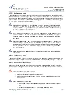
The 10/100 Ethernet interface is a standard interface that connect to a computer Ethernet port,
Ethernet Switch/Router, Ethernet to Wi-Fi module, non-certified Ethernet compatible display,
etc. The Ethernet interface is uncertified and therefore an only connect to
devices supporting
non-certified functionality
such as MPI or un-certified traffic and FIS-B information display on
portable devices.
Ethernet Interface
PIN
SIGNAL
ELECTRICAL
I/O
DESCRIPTION
J1-21
Ethernet RX+
Ethernet
I
Ethernet Port R
J1-20
Ethernet RX-
Ethernet
I
Ethernet Port Receive -
J1-42
Ethernet TX+
Ethernet
O
Ethernet Port Tr
J1-41
Ethernet TX-
Ethernet
O
Ethernet Port Transmit -


