


25
HOW TO MANAGE CONSOLE FIRMWARE
Firmware is the programming that allows the console
and sensor to function. Using the firmware menu, you
can do the following:
• View information about the console firmware and
the power sensor firmware
• Import upgraded firmware
• Save and import custom console settings
• Restore console settings to the manufacturer’s
default settings
The firmware menu contains the following menu
options:
CNSL V.X (console version number)
—Select this
menu option to view the current firmware version num-
ber for the console.
PWR V.X (power sensor version number)
—Select
this menu option to view the current firmware version
number for a power sensor paired to the console.
UPGRD FIRMWARE
—Select this menu option to
replace the current firmware with upgraded firmware.
See HOW TO UPGRADE FIRMWARE at the right.
SAVE CONFIG
—Select this menu option to save your
custom console settings to a USB drive. Your custom
console settings can then be used on other consoles.
See HOW TO SAVE CUSTOM CONSOLE SETTINGS
on page 26.
IMPRT CONFIG
—Select this menu option to import
saved custom console settings from a USB drive
into the console. See HOW TO IMPORT CUSTOM
CONSOLE SETTINGS on page 26.
RESET TO DEFAULT
—Select this menu option to
reset your custom console settings to the manufac-
turer’s default settings. See HOW TO RESTORE
DEFAULT SETTINGS on page 27.
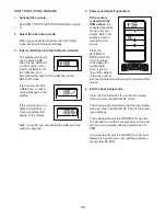
How to Upgrade Firmware
IMPORTANT: Upgrading the firmware is an
advanced procedure. Make sure to read all instruc-
tions before upgrading the firmware.
1. The manufacturer will provide the upgraded firm-
ware file in a specific xxxx.HEX file format.
2. You must save the file on a USB drive. The file
must be in the top level of the drive directory. The
file cannot be within any other folder. You can save
only one firmware file on the USB drive at a time.
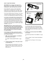
3. Make sure that the USB port on the console is
enabled (see step 3 on page 24).
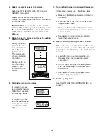
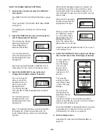
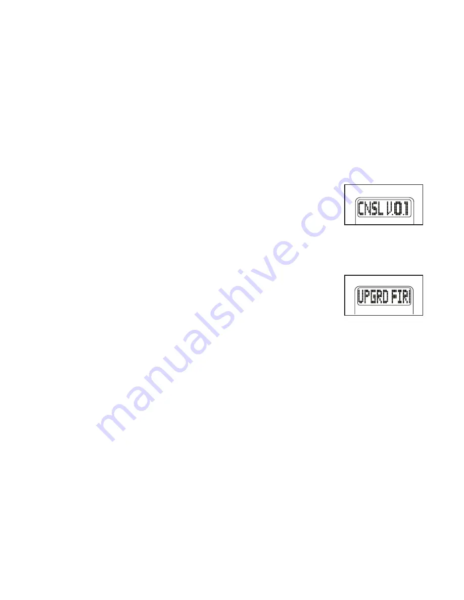
4. Select the CNSL V.X
menu option on the
firmware menu. View
and note the cur-
rent console version
number.
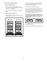
5. Insert the USB drive containing the upgraded firm-
ware file into the USB port on the console.
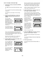
6. Select the UPGRD
FIRMWARE menu
option on the firmware
menu. The console
will begin the firmware
upgrade.
7. During the firmware upgrade, the LCD display
will freeze for approximately 10 seconds and
then all the displays will light for a moment. After
this occurs, the console is using the upgraded
firmware.
8. Select the CNSL V.X menu option on the firmware
menu. View and note the upgraded console version
number.
9. Restore your custom console settings if desired.
During the firmware upgrade, the console settings
will be reset to the manufacturer’s default settings.
Note: If the console has been paired to a sensor,
you do not need to re-pair the console to the sen-
sor; the paired relationship will survive the firmware
upgrade.