background image

14

Note: Specifications are subject to change without notice. For information about ordering replacement parts, see 
the back cover of this manual. *These parts are not illustrated. 

 Key No.  Qty. 

Description


Key No.  Qty. 

Description


Tower


Upper Cover


Lower Cover


Cap


Long Magnet Strip


Short Magnet Strip


Base


Wear Cover


Pulley Bracket Guide


10 

Weight Guide


11 

Weight Carriage


12 

5-pound Weight


13 

Weight Pin


14 

Foot


15 

Weight Guide Bushing


16 

Small Aluminum Pulley


17 

Large Aluminum Pulley


18 

Small Cable Trap


19 

Large Cable Trap


20 

Foot Strap


21 

Weight Bumper


22 

Access Cover


23 

Cable End


24 

Platform Base


25 

Pulley Carriage


26 

Platform


27 

Long Cable


28 

Short Cable


29 

V-pulley


30 

Linear Bearing


31 

Pulley Bracket Bumper


32 

Clamp


33 

Cable Cover


34 

Handrail


35 

Rail Cover


36 

Flange Bushing


37 

Internal Snap Ring


38 

3/8" Serrated Washer


39 

3/8" Jam Nut


40 

Roller


41 

Roller Axle


42 

1/2" x 1" Button Screw


43 

10 

10-pound Weight


44 

3/8" x 2 1/2" Screw


45 

Quick Link


46 

3/8" Locknut


47 

1/2" x 1" Screw


48 

10 

3/8" x 1/2" Screw


49 

1/2" x 4" Screw


50 

3/8" x 2 1/4" Bolt


51 

3/8" x 1 3/4" Bolt


52 

3/8" Jam Locknut


53 

Cap Fastener


54 

5/8" Split Washer


55 

5/8" Jam Nut


56 

1/4" x 3/8" Screw


57 

#8 x 3/8" Screw


58 

3/8" Black Jam Locknut


59 

Dual Cable Trap


–– 

Owner’’s Manual

PART LIST

Model No. F707.0 R0413B

Summary of Contents for Hamstring F707.0

Page 1: ... the space above for reference CAUTION Read all precautions and instruc tions in this manual before using this equipment Keep this manual for future reference QUESTIONS If you have questions or if parts are damaged or missing please see HOW TO CONTACT CUSTOMER CARE on the back cover of this manual OWNER S MANUAL ...

Page 2: ...N IP Inc IMPORTANT PRECAUTIONS 3 WARNING DECAL PLACEMENT 4 BEFORE YOU BEGIN 5 MAINTENANCE AND TROUBLESHOOTING 6 CABLE DIAGRAM 10 PART LIST 14 EXPLODED DRAWING 15 HOW TO CONTACT CUSTOMER CARE Back Cover LIMITED WARRANTY Back Cover TABLE OF CONTENTS ...

Page 3: ... the strength equipment at all times 9 Always wear athletic shoes for foot protec tion while exercising 10 Keep hands and feet away from moving parts Do not lean on or rest your hands on the strength equipment while it is in use 11 Make sure that the weight pin is completely inserted into one of the weights 12 Make sure that the foot strap is attached securely before each use of the strength equip...

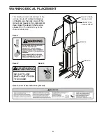
Page 4: ...n s of the warning decal s If a decal is missing or illegible see the back cover of this manual and request a free replacement decal Apply the decal in the location shown Note The decal s may not be shown at actual size DO NOT USE MACHINE FROM THIS SIDE WARNING Decal 1 Decal 2 Decal 3 Decal 4 Part of the instruction placard ...

Page 5: ...ively For your benefit read this manual carefully before using the strength equipment If you have questions after reading this manual please see the back cover of this manual To help us assist you note the product model number and serial number before contacting us The model number and the location of the serial num ber decal are shown on the front cover of this manual Before reading further pleas...

Page 6: ...ed FreeMotion Fitness and its vendors cannot be held liable for injuries or damage resulting from the use or misuse of cleaning products IMPORTANT When using any cleaning product try it first in a hidden place to ensure that there is no damage to the material Do not use abrasive cleaners strong cleaners or solvents such as lacquer thinner kerosene gasoline or similar liquids Such substances may sc...

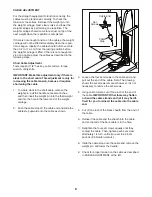
Page 7: ...tives are LUBRIPLATE MAG 00 76 DYNALIFE L EP 000 CASTROL HD 000 and SUPER LUBE 00 000 grease IMPORTANT To avoid permanently damag ing the linear bearings do not use any other type of grease 1 Using a soft cloth clean the pulley bracket guide make sure to remove the accumulated grease and debris from the ends of the pulley bracket guide 2 Insert the weight pin into the weight stack and have a secon...

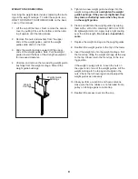
Page 8: ... in the short cable remove the weight pin pull the handle out several inches and then insert the weight pin into the third weight and into the hole in the lower end of the weight carriage 2 Push the cable stop off the cable end and slide the cable stop upward onto the cable as shown 3 Loosen the four set screws in the cable end and pull out the end of the cable Note The drawing shows the set screw...

Page 9: ...weight guide bushings If they are overtightened they may make a chattering noise when they move on the weight guides 6 Clean and lubricate the weight guides by wiping them with a soft cloth containing 10W 40 or 10W 30 lightweight motor oil Apply only a light coating over the entire length Do not use based lubri cants 7 Replace the weight carriage on the weight guides 8 Reattach the weight guides t...

Page 10: ... each cable Use the diagram to make sure that the cables and the cable traps are assembled correctly If a cable is not cor rectly routed the strength equipment will not function properly and damage may occur Make sure that the cable traps do not touch or bind the cable 1 1 2 2 3 3 Long Cable 27 Short Cable 28 4 ...

Page 11: ...11 NOTES ...

Page 12: ...12 NOTES ...

Page 13: ...13 NOTES ...

Page 14: ...1 2 Weight Bumper 22 1 Access Cover 23 1 Cable End 24 1 Platform Base 25 1 Pulley Carriage 26 1 Platform 27 1 Long Cable 28 1 Short Cable 29 1 V pulley 30 2 Linear Bearing 31 2 Pulley Bracket Bumper 32 2 Clamp 33 1 Cable Cover 34 2 Handrail 35 4 Rail Cover 36 2 Flange Bushing 37 2 Internal Snap Ring 38 1 3 8 Serrated Washer 39 1 3 8 Jam Nut 40 1 Roller 41 1 Roller Axle 42 4 1 2 x 1 Button Screw 43...

Page 15: ...9 14 14 44 44 29 28 28 16 23 30 32 32 25 53 27 31 31 36 36 37 37 46 48 48 52 52 51 56 57 57 56 56 22 20 45 33 59 50 58 46 11 10 12 13 15 21 54 55 55 43 19 18 17 51 49 3 2 26 24 40 41 47 47 42 35 34 EXPLODED DRAWING Model No F707 0 R0413B ...

Page 16: ...xcess of the maximum user weight listed in this manual Note This product may not have a maximum user weight 5 Damage caused by moving the product or improper stor age including moving or storing the product on its side 6 Use or storage of the product outdoors or in high humidity environments including spa and pool areas 7 Damage caused by improper wiring or insufficient electri cal current Note Th...

Reviews: