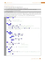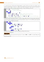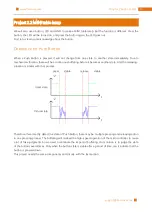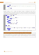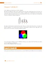
Chapter 3 LEDBar Graph
72
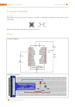
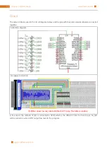
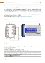
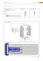
Circuit
The network label is used in the circuit diagram below, and the pins with the same network label are connected
together.
Schematic diagram
Hardware connection
In this circuit, the cathode of LED is connected to GPIO, which is the different from the front circuit. So, LED
will be turned on when GPIO output low level in the program.
If LEDbar doesn’t work, rotate LEDbar 180° to try. The lable is random.
Summary of Contents for Ultimate Starter Kit
Page 1: ...Free your innovation Freenove is an open source electronics platform www freenove com ...
Page 117: ...117 Chapter 9 Potentiometer RGBLED www freenove com support freenove com Hardware connection ...
Page 155: ...155 Chapter 14 Relay Motor www freenove com support freenove com Hardware connection OFF 3 3V ...
Page 173: ...173 Chapter 16 Stepping Motor www freenove com support freenove com Hardware connection ...
Page 239: ...239 Chapter 22 Matrix Keypad www freenove com support freenove com Circuit Schematic diagram ...
Page 240: ...Chapter 22 Matrix Keypad 240 www freenove com support freenove com Hardware connection ...

