99
Chapter 7 AD/DA Converter
Chapter 7 AD/DA Converter
We have learned how to control the brightness of LED through PWM and understood that PWM is not the
real analog before. In this chapter, we will learn how to read analog quantities through AD/DA Module,
convert it into digital quantity and convert the digital quantity into analog output. That is, ADC and DAC.
Project 7.1 Read the Voltage of Potentiometer
In this project, we will use the ADC function of AD/DA Module to read the voltage value of potentiometer.
And then output the voltage value through the DAC to control the brightness of LED.
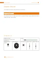
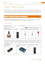
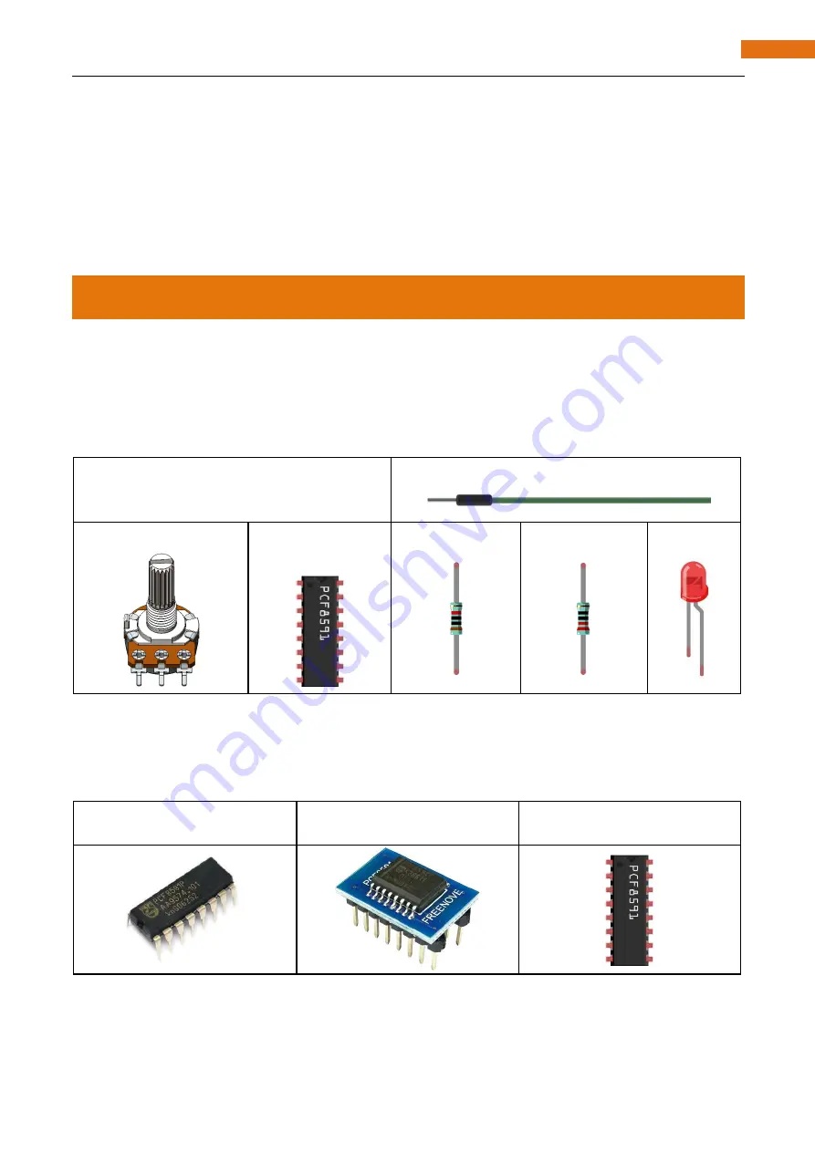
Component List
Raspberry Pi 3B x1
GPIO Extension Board & Wire x1
Breadboard x1
Jumper
Rotary potentiometer x1
PCF8591 x1
Resistor 10kΩ x2
Resistor 220Ω x1
LED x1
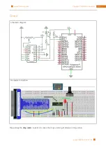
Below are physical diagram and model diagram of AD/DA converter. There are two different package forms
for PCF8591. Now PCF8591 with SO16 to DIP16 package is included in this kit. Model diagram is used in the
circuit diagram. When using, just keep direction and position the same. The direction can be judged by the
gap on the chip.
PCF8591P (DIP16)
(
Retired soon
)
PCF8591T (SO16 to DIP16)
(Usually)
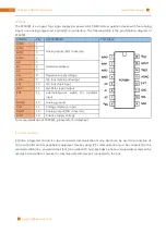
Model diagram of PCF8591
Summary of Contents for Ultimate Starter Kit
Page 1: ...Free your innovation Freenove is an open source electronics platform www freenove com ...
Page 117: ...117 Chapter 9 Potentiometer RGBLED www freenove com support freenove com Hardware connection ...
Page 155: ...155 Chapter 14 Relay Motor www freenove com support freenove com Hardware connection OFF 3 3V ...
Page 173: ...173 Chapter 16 Stepping Motor www freenove com support freenove com Hardware connection ...
Page 239: ...239 Chapter 22 Matrix Keypad www freenove com support freenove com Circuit Schematic diagram ...
Page 240: ...Chapter 22 Matrix Keypad 240 www freenove com support freenove com Hardware connection ...

